Personal systems projectDrawing 15.1 of 25Part 1 of 3
Video pipeline
Photons to display: the exposure solve, the stitch, late reprojection, and the forty five milliseconds all of it has to fit inside.
Specification / as recorded
Status
In development, 2026
Role
Solo
Written
About 129,000 lines of hand-written C++17 across 15 subsystems
Desktop tests
105 run, 105 pass, on a laptop with no sensor attached
Not run on hardware
Zero lines. Every performance figure below is a budget
Owned
The helmet display. Everything else is still unbought
Target
Jetson Orin Nano 8GB worn on the body, Raspberry Pi 5 on the robot
Sheet 02 of 04/Pipeline
Photons to display
The video path is the hot loop and everything else is scheduled around it.
Capture, then a cross camera exposure solve, then the stitch, then blending, then thermal registration and composite, then the HUD raster, then the per eye present, then the flip. The canvas is 2560 by 1200. The display is a Wisecoco dual 3.81 inch AMOLED, 1080 by 1200 per eye, presented over HDMI to MIPI as one 2160 by 1200 panel. It is the one piece of hardware I own.
PlatePL-01
TitleSame canvas presented per eye
ViewDetail
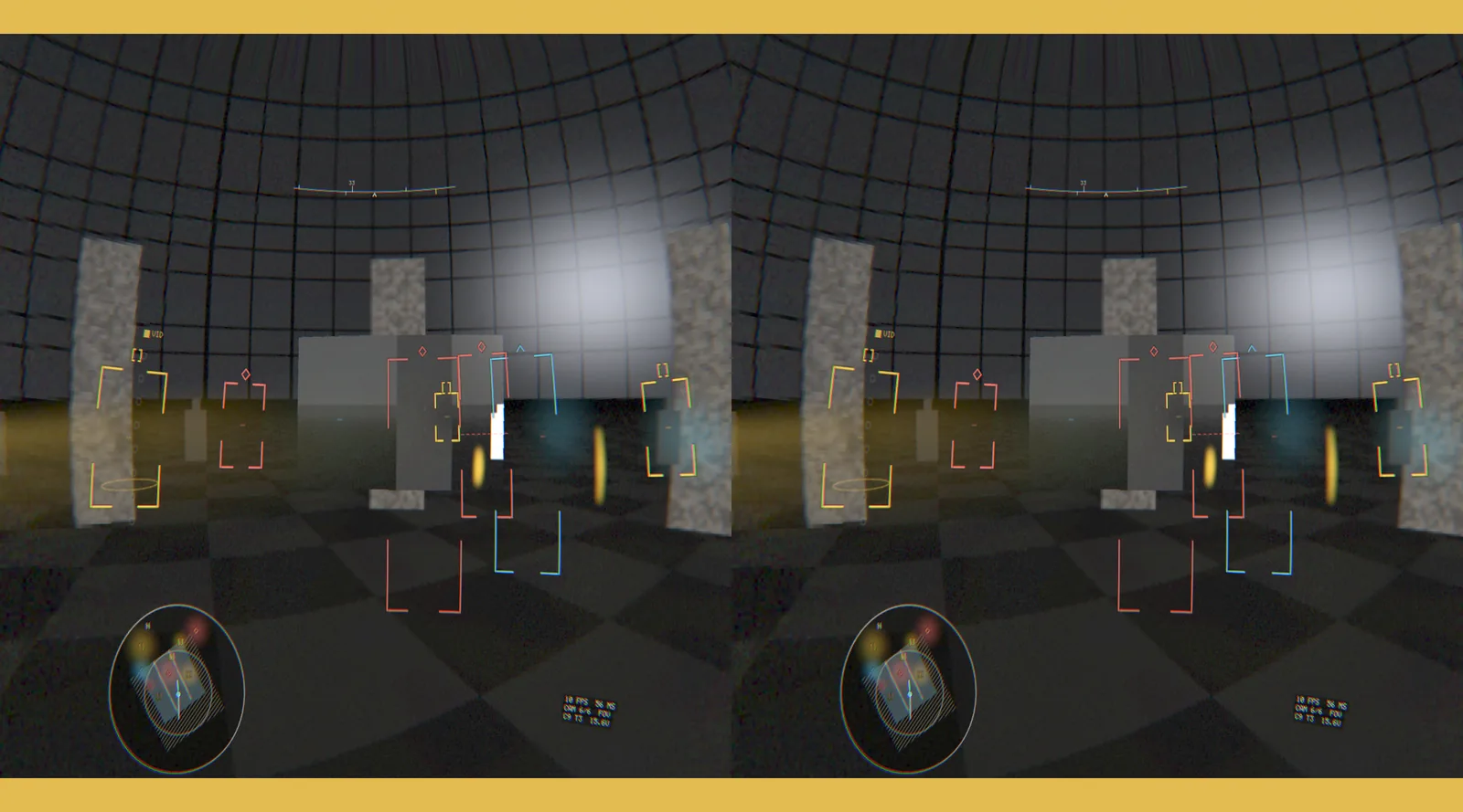
Barrel pre-distortion cancels the viewing lens, and the amber bands top and bottom are the degraded warning, firing here because a laptop cannot hold 60 Hz.
Four things in that path are worth pulling out, because each of them exists to defeat a specific failure.
The exposure solve happens before the stitch, not after
Six sensors with independent auto exposure produce six different brightnesses, and a brightness step across a seam is a hard vertical line your eye locks onto instantly. So a six variable damped Gauss-Seidel solve runs over pre-computed overlap samples every frame and flattens the gains. It is budgeted at about 0.3 ms. It is also carefully distinguished from geometric seam error in the calibration document, because the two look nothing alike and the fixes are unrelated: if the seam is a brightness step, re-running the extrinsics calibration is wasted effort.
Binning is a low light win, not a compromise
The IMX678's array is 3840 by 2160 and the pipeline bins it on the sensor to roughly two megapixels. That is not a concession to bandwidth. Two by two binning sums four photodiodes, which in the shot noise limited regime is about a stop of signal to noise, on a sensor chosen specifically for low light, in an arena that is specifically dark. The bandwidth saving and the image quality gain are the same decision. Doing it on the sensor also means those pixels never cross the camera interface at all.
The catch is that binning and cropping change the intrinsics: the focal lengths scale and a crop shifts the principal point. Get that wrong and the stitch lookup table is built against a lens that does not exist, the seams are off by a few pixels everywhere, and no amount of extrinsic re-calibration fixes it because the error is in the wrong parameter. One function is allowed to do that math and nothing is allowed to open-code it.
Reprojection is the architecture, not a feature
Two different corrections, applied to two different layers, for two different reasons.
The thermal core runs at 60 Hz but adds about a frame of its own latency. Compositing a 16 ms old thermal image onto a fresh panorama means that during a head turn, warm bodies smear off the people they belong to, exactly when you are turning to look at them. So the head's angular rate is integrated over the thermal frame's measured age, not an assumed 16 ms, and the thermal to canvas mapping is rotated by that delta before sampling. It costs one 3 by 3 matrix update per frame and it is the cheapest latency reduction anywhere in the pipeline.
The visible layer gets the much bigger correction, and it is the highest leverage thing in the whole subsystem. Pipeline latency and perceived latency are different numbers, and only the second one makes a person sick. Capture through stitch through fusion through HUD is unavoidably deep, because exposure alone is 8 ms. So immediately before scanout the freshest head pose is sampled again and the finished composite is re-warped onto it. Perceived motion-to-photon then approaches one frame no matter how deep the pipeline behind it is.
It is six degrees of freedom rather than rotation only, because a stereo depth map is available, which is better than most consumer headsets manage. And it runs on a separate, higher priority path from the pipeline, so if the pipeline misses a frame the reprojection still runs, on the last good composite, against a fresh pose. A stall becomes a slightly stale image instead of visible judder, and it composes correctly with the degraded fallback, because the reprojector never needs the pipeline to be alive to keep the world moving with your head.
The implementation detail I like is that the warp is computed on a coarse 16 pixel grid, about ten thousand vertices, with the per pixel sampling coordinate interpolated between them. Doing the exact ray transform per pixel would be around 70 million multiplies per frame and does not fit. The coarse grid also solves a problem it was not aimed at: a per pixel six degree of freedom reprojection tears holes at depth discontinuities, where translation reveals surfaces the camera never saw, while interpolating depth across grid cells smears across them instead. A small stretch at a depth edge is much better than a hole.
In the harness it reports what it did. Over one run: reprojection enabled, 240 passes, a peak head rate of 139 degrees per second, and up to 2.29 degrees of head rotation corrected per scanout. Without it, the image would have lagged by about 9.6 degrees.
The project's own latency document argues the exact opposite, that the visible layer must never be reprojected because the canvas is already the freshest observation that exists. The code disagrees with it, in a header that calls reprojection the architecture rather than a feature. I have written the page from the code, because the code is the thing that runs, but the two need reconciling and I have not done it.
A dead camera is drawn as a hole
PlatePL-02
TitleCamera two, killed mid run
ViewDetail
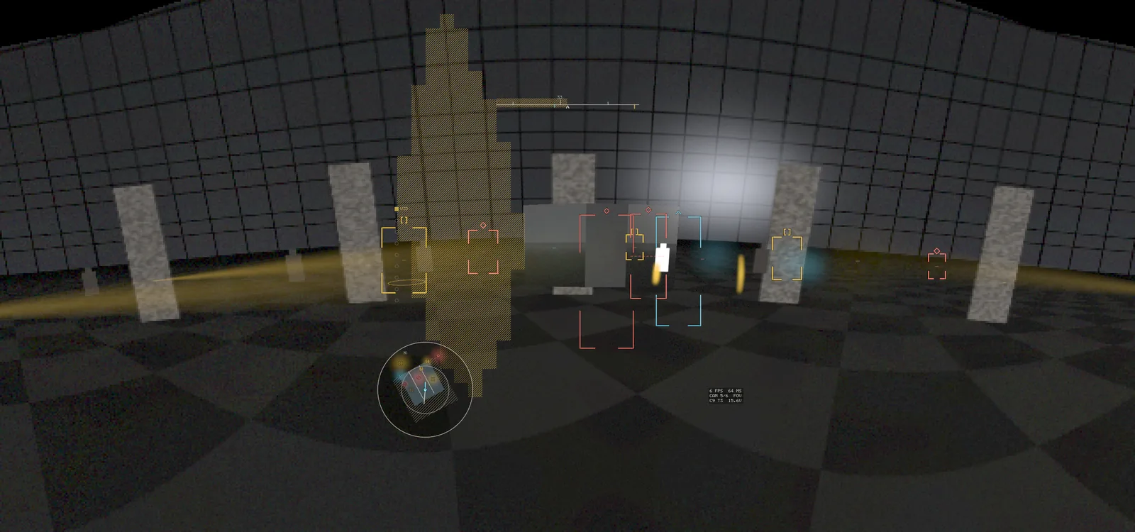
The stitch marks the dead sector with a hatched amber wedge rather than interpolating over it, and the status readout drops from CAM 6/6 to CAM 5/6.
Rolling shutter is corrected per scanline, because line y was captured later than line 0 and vertical lines lean during head turns otherwise. The correction is applied to the canvas sampling coordinate, and it is emphatically not electronic image stabilisation, which is banned outright on this path for reasons in the safety section.
Sheet 03 of 04/Latency
Forty five milliseconds, at the ninety ninth percentile
The gate is motion-to-photon under 45 ms at p99. Not the mean.
That distinction is the whole point. A rig with a 30 ms mean and a 90 ms p99 feels broken, because every hundredth frame is a lurch and the vestibular system notices every one of them. A rig at 38 ms mean and 42 ms p99 feels solid. The mean cannot tell those two apart.
Above roughly 50 ms, disorientation and nausea set in, in a wearer who is running indoors with no unmediated view of the floor. The mechanism is worth understanding rather than taking on faith. The vestibulo-ocular reflex stabilises your gaze against head motion on a loop latency of about 10 ms, involuntarily, calibrated over a lifetime to the assumption that the world is rigid. A passthrough helmet breaks that assumption: the vestibular system reports that you turned nine degrees while the retina reports that the world turned nine degrees, 45 ms ago. The error signal has nowhere to go, and the resolution the brain reaches, over minutes rather than seconds, is nausea.
A brisk head turn is about 200 degrees per second. At 45 ms that is nine degrees of angular error, which at the tracker's working figure of roughly 19 pixels per degree is about 170 pixels of positional lag. That is already large. It is tolerable only because it is consistent: everything lags by the same amount, so the scene stays internally rigid. What breaks tolerance is differential lag, where the thermal layer or a target outline lags relative to the visible scene. That is why the timewarp exists.
The budget totals 28.1 ms typical and 38.8 ms at p99, which leaves about 6 ms of headroom against the gate. It is not comfortable, and it assumes every stage hits its number. The tighter constraint is inside the frame: the per frame compute stages have to fit in one 16.6 ms period or the pipeline drops a frame, and they occupy 50% of it typically and 78% at p99. Seventy eight percent is where the frame drop tail lives, and it is the integration risk this project actually has: every subsystem looks fine alone and collectively blows the budget. So stage timings are collected in release builds always, never behind a debug flag. Two clock reads per stage against a 16.6 ms budget costs nothing, and the alternative is finding out in the arena.
The measurement I have cannot be trusted, and I know by how much
Software timestamps under-report on this system, systematically, in the flattering direction, by roughly half.
There is a blind spot at each end. At the front, whether the capture timestamp is really the shutter midpoint depends entirely on the driver: a good path latches it in hardware, a mediocre one stamps it when user space got the buffer, which hides nine to twelve milliseconds of exposure, readout and transfer. Nothing in software can distinguish a hardware latched timestamp from a convincingly placed software one. At the back, the last thing software can see is the page flip, which is when scanout starts. The top row of the panel lights immediately and the bottom row lights 16.6 ms later, and the panel then holds the frame for the whole refresh period because generic driver boards do not strobe.
Those invisible stages total about 18.3 ms of a 28.1 ms budget. So a software-only measurement can plausibly report 10 ms on a rig genuinely at 28, or 30 ms on a rig genuinely at 80. The second one is the failure that matters: that is a rig that ships feeling awful while the dashboard says it is fine.
The only trustworthy instrument is about ten dollars of parts: flash an LED, watch the panel with a photodiode, measure the interval. Until that has been run, the honest answer to "what is your latency" is that I do not know.
Sheet 04 of 04/Bandwidth
The constraint is memory bandwidth, not TOPS
The Orin Nano 8GB is marketed on 67 TOPS. That number is close to irrelevant to whether this works.
The real constraint is about 68 GB/s of LPDDR5 shared between the CPU, GPU, image processor, vision accelerators and the display controller, and you do not get 68. Achievable streaming bandwidth is typically 60 to 70 percent of peak once refresh, page misses and concurrent masters are accounted for, so the budget is written against about 45 GB/s.
The reason the pipeline is memory bound rather than compute bound falls out of the arithmetic intensity. Per output pixel the stitch gather moves roughly 12 bytes of lookup table, 8 bytes of source pixel and 4 bytes of canvas write: about 24 bytes moved to perform one weighted blend. That is well under one floating point operation per byte. Every stage in this pipeline has that shape, a streaming pass over multi megabyte buffers with almost no arithmetic per byte. None of them come anywhere near the compute ceiling.
Meanwhile the thing the TOPS number is actually for, the person detector at INT8 on a 640 by 512 thermal frame, is one to two billion operations per inference. At 25 Hz that is around 50 GOPS, which is under 0.1% of the advertised capability. The detector is not the problem. Feeding the pipeline is.
The full ledger comes to about 14.4 GB/s, roughly 32% occupancy, which is workable but not roomy and does not include the operating system or the four soft real time processes. The same ledger with the cameras run at full resolution instead of binned comes to about 32 GB/s, over 70% of achievable, to deliver pixels that are thrown away in the very next resample. That is the cliff, and it is why the sensor bins.
Two consequences follow directly, and both of them are the kind of thing you only see if you count bytes rather than operations:
Offloading the stitch to the fixed function accelerators saves occupancy, not bandwidth. It frees the GPU for the detector, which is worth doing, but those accelerators read and write the same memory. Not one byte of traffic goes away. The only way to reduce bandwidth is to move fewer pixels.
The lookup table is a first class cost. At 6 bytes per tap and two taps, so 12 bytes per pixel across a 2560 by 1200 canvas, it is 36.9 MB, read in full every frame. That is 2.2 GB/s, and it is the largest single buffer the pipeline re-reads in its entirety every frame. That is why the stitch takes two taps and not four: three camera overlaps are rare enough that clamping to the best two is invisible, and doubling the taps would double that line, putting it above the capture and source reads that currently sit at 3.3 GB/s each. It is also why the source coordinates are stored as fixed point rather than float. A sixteenth of a pixel is well under the calibration's own residual error, so the quantisation is free and it halves the table.