Machine tool designDrawing 32 of 33
3/4/5-axis
CNC machine
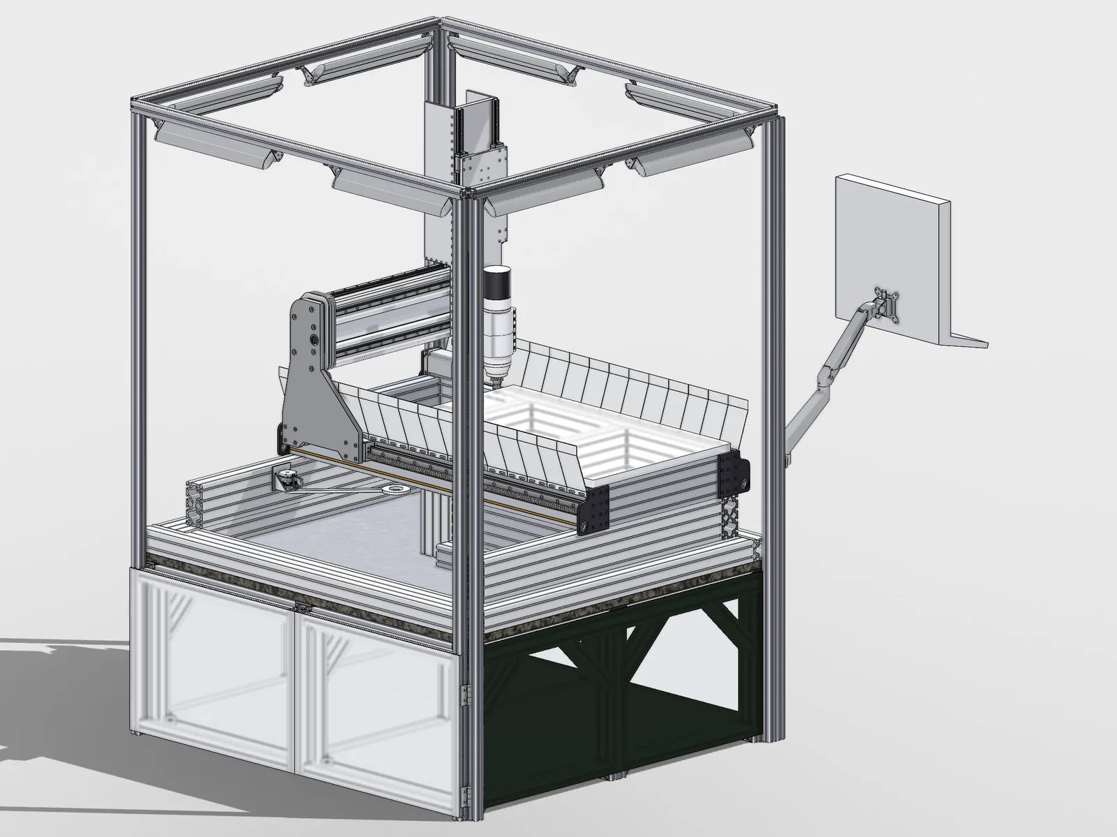
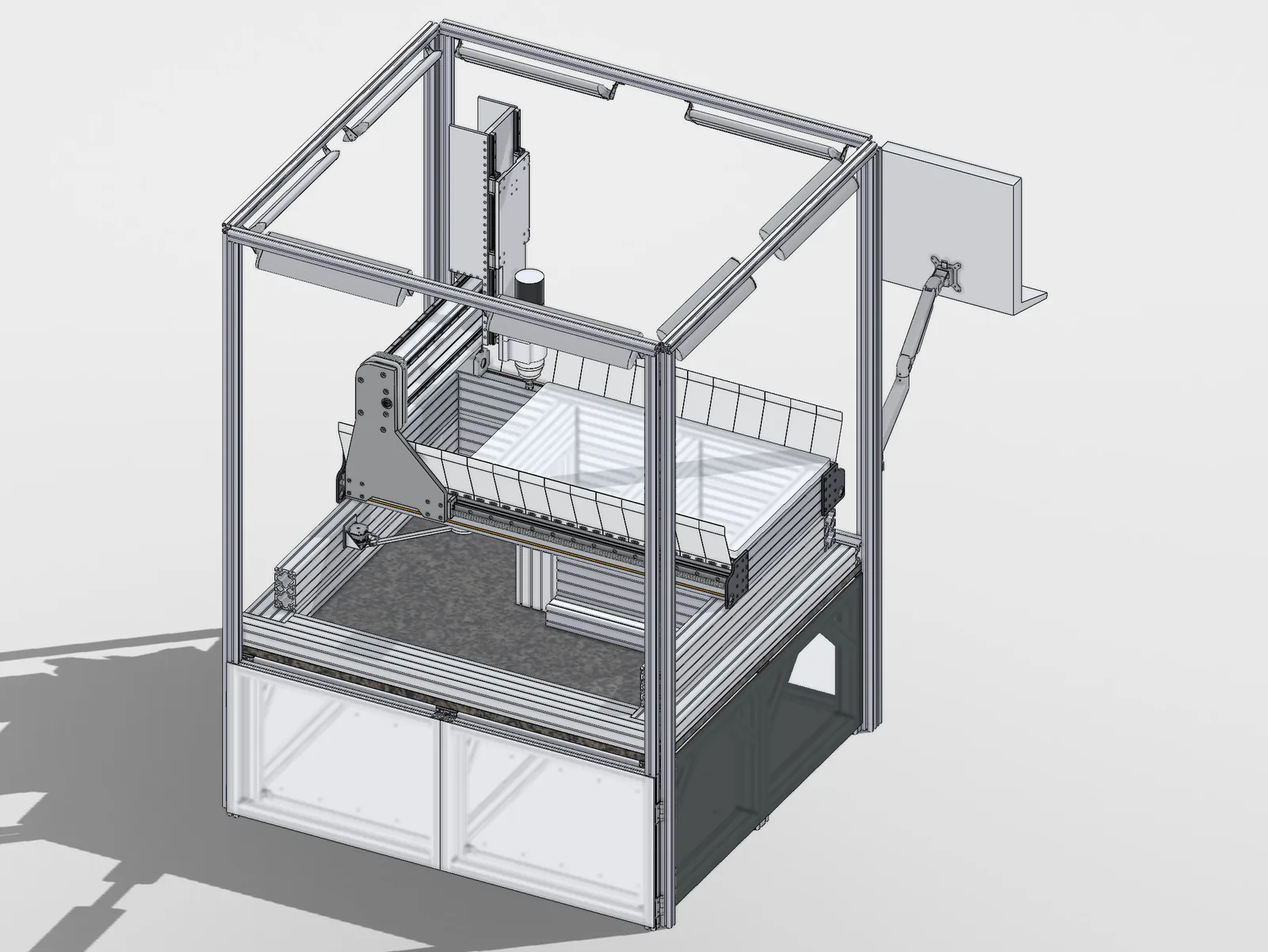
A CNC mill I'm designing from scratch, so I can make the parts I want. The table on top lets it machine plates, and there are three bays underneath: one for the tool changer, one for 4-axis machining and one for 5-axis machining. It's still in development. So far it's about 40 hours of general design and about 60 hours of research and development, I expect it to cost around $7,000 to build, and I plan to build it within a year.
- StatusIn development, modelled in SolidWorks, not built
- Time so farAbout 40 hours of design and 60 hours of research and development
- Expected costAround $7,000
- Build planWithin a year
- Work area1000 x 600 mm
- Spindle4.5 kW BT30 tool-change, water-cooled
- ControlLinuxCNC on a Mesa 7i96S and 7i76U
- What does not existA built machine, the trunnion, the tool rack
Sheet 02 of 11/The brief
What it has to cut
The machine is sized for three jobs: aluminium plate parts up to 30 mm thick, one-off prototypes in mixed materials, and foam carved for molds. The trunnion adds tilted plate and block work on top of that.
Sheet 03 of 11/Layout
Why the gantry spans the short side
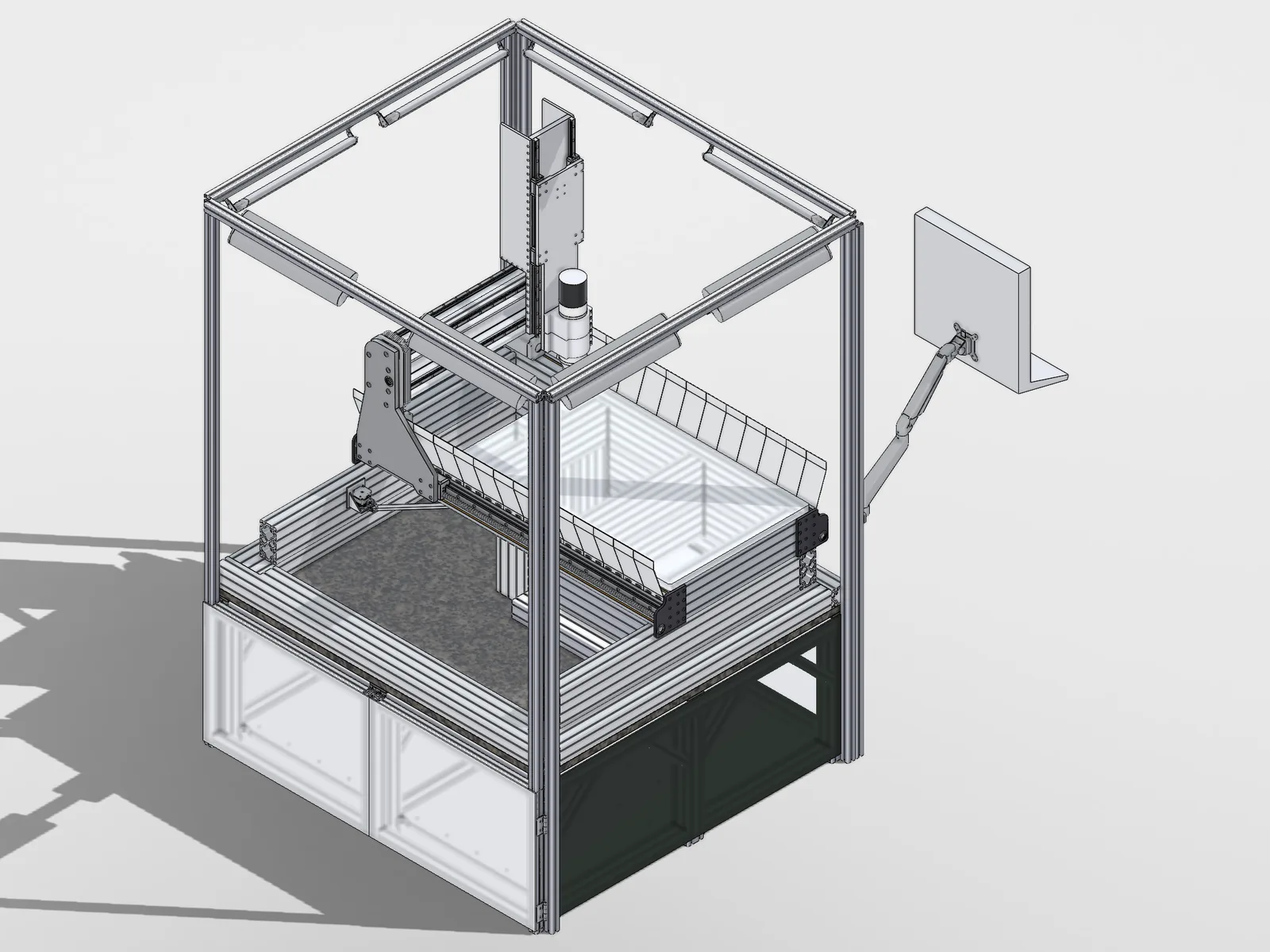
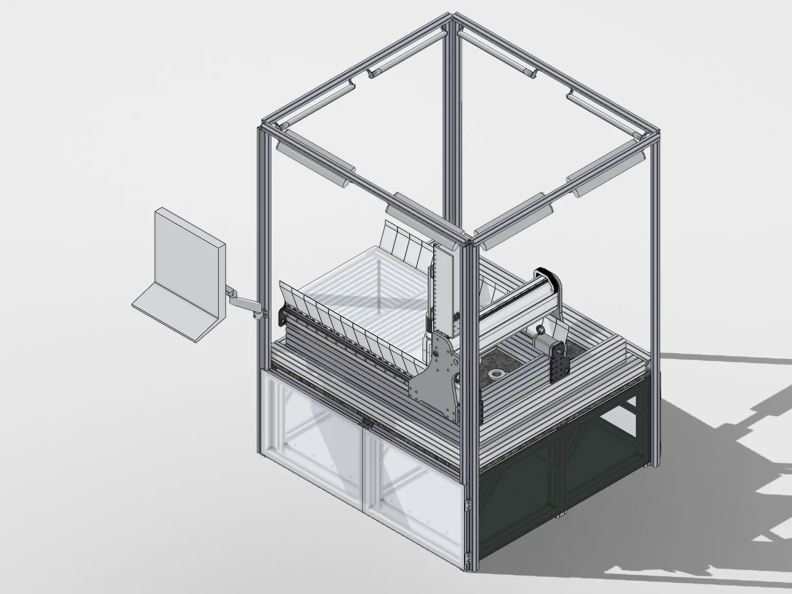
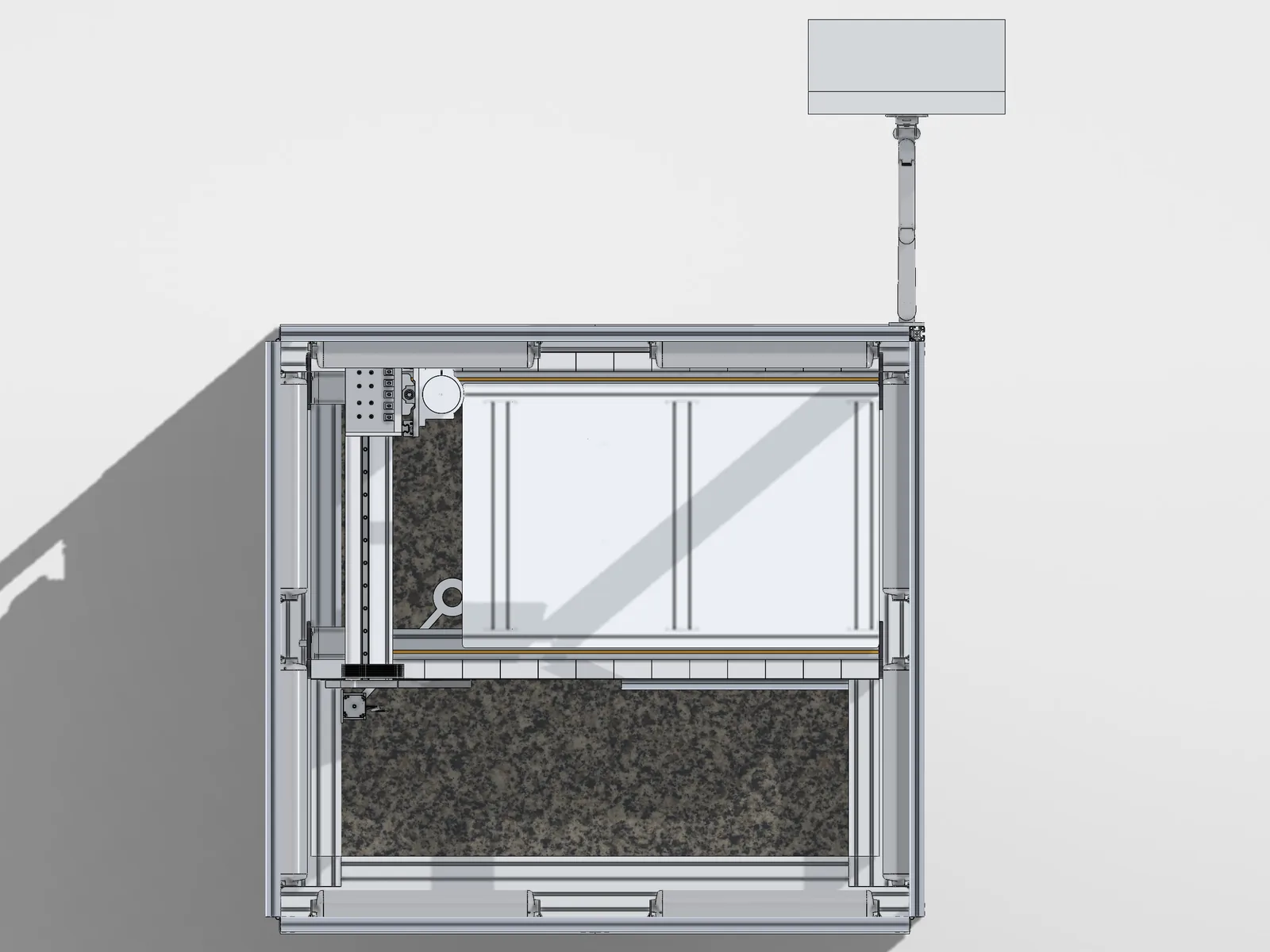
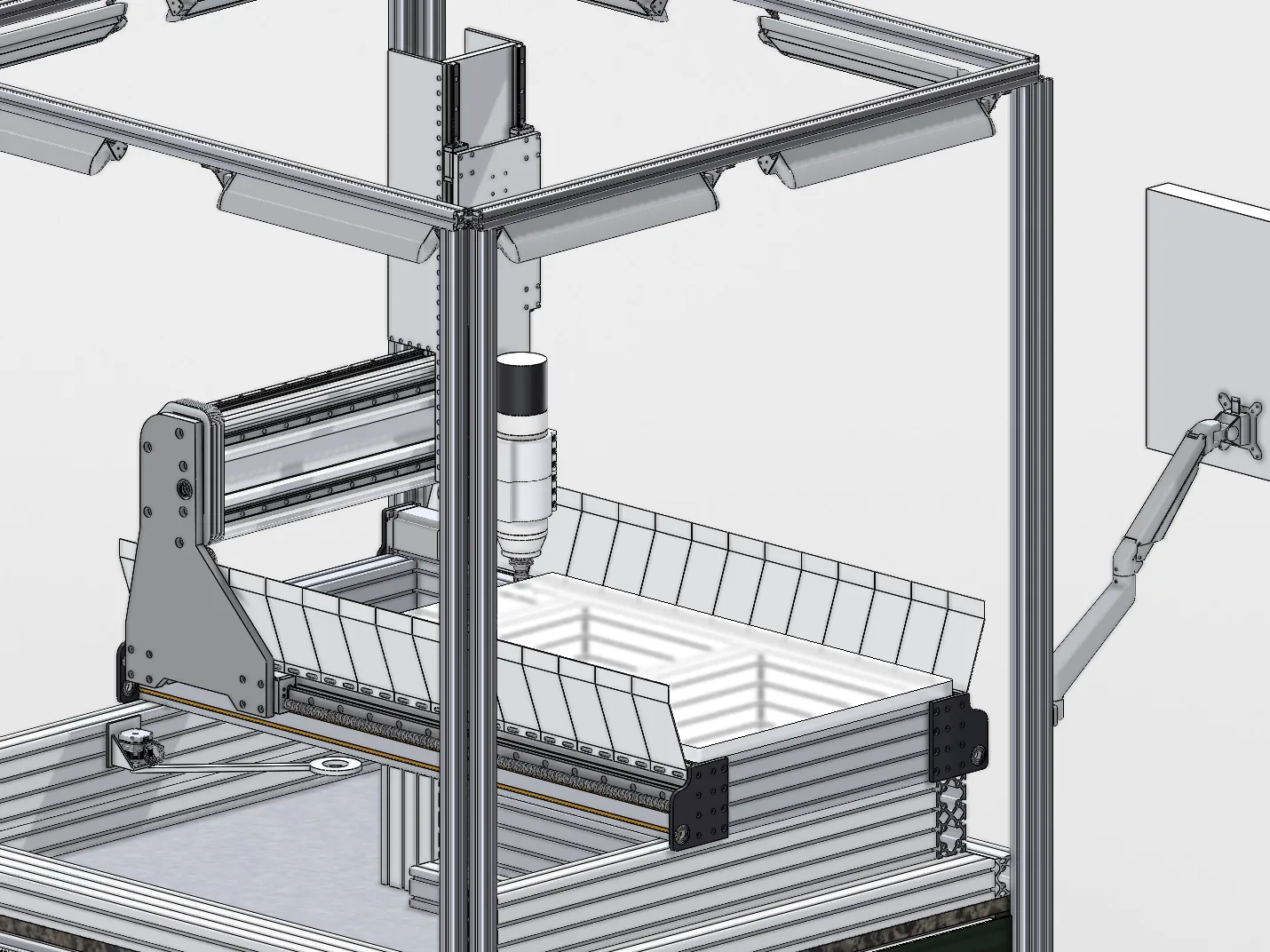
The gantry spans the 600 mm side of the work area and travels the 1000 mm one. Beam deflection goes with span cubed, so spanning 600 mm instead of 1200 mm cuts it by 8x.
The table stays put and the gantry moves. A moving table would have needed about 2 m of floor to travel through, for no stiffness gain at a 600 mm span.
Sheet 04 of 11/Stiffness
The cutter is the softest spring
Every part of the machine bends like a spring, and they add in series, so the softest one sets the answer. With a 6 mm tool, the softest one isn't in the frame at all, it's the cutter.
| Cutter | Stickout | Stiffness |
|---|---|---|
| 6 mm carbide | 20 mm | 5.9 N/um |
| 6 mm carbide | 30 mm | 1.7 N/um |
| 10 mm carbide | 25 mm | 23.2 N/um |
| 12 mm carbide | 30 mm | 27.8 N/um |
A 6 mm cutter at 20 mm out is softer than the whole frame target, so the frame stops at 8 to 12 N/um instead of chasing 20. The cheapest stiffness on the machine is stickout: pulling the same 6 mm tool in from 30 mm to 20 mm makes it 3.5x stiffer.
Sheet 05 of 11/Frame
Bolted extrusion, not welded steel
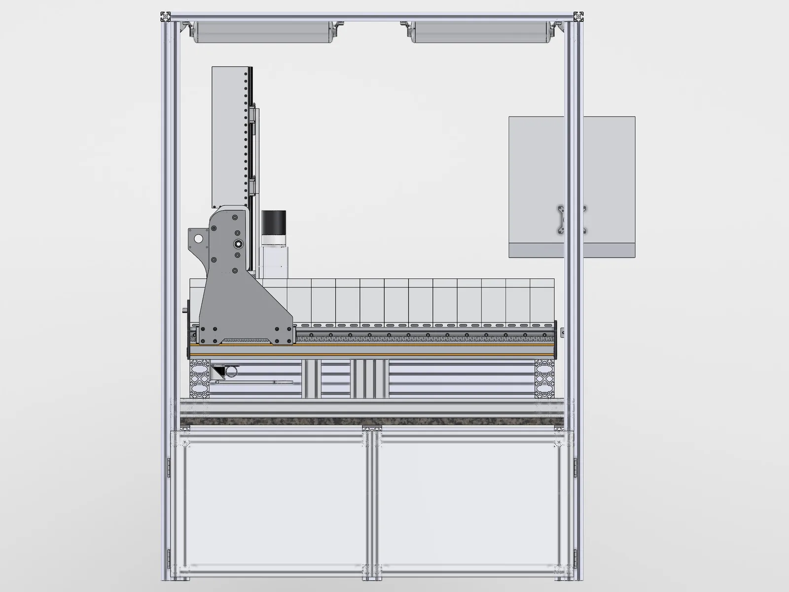
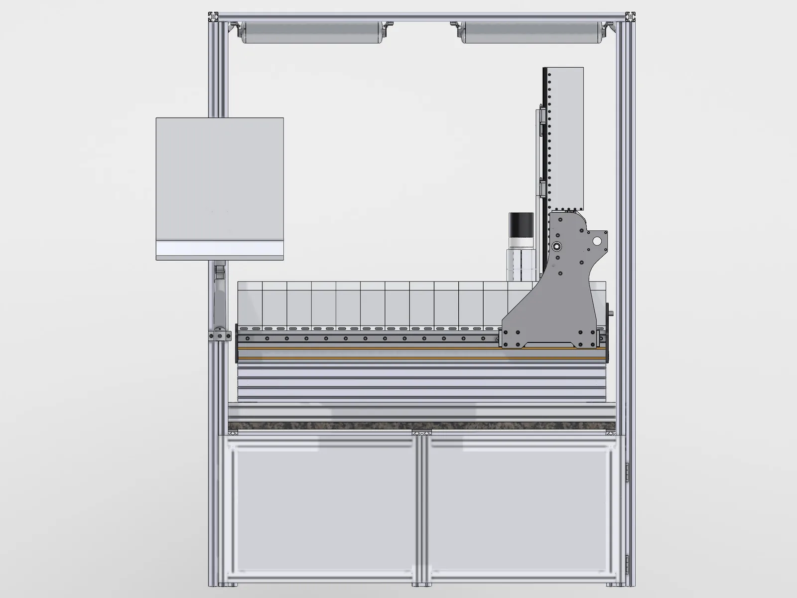
The first spec called for welded steel tube filled with epoxy granite. I went with bolted 80x160 aluminium T-slot instead, gusseted at every joint, with sand or resin fill for damping. At a 600 mm span the beam isn't the weak point, the joints are, so every joint gets a gusset.
The accuracy budget lands around 0.05 to 0.1 mm, which is a good hobby mill and not a precision machine. The biggest single term is heat: an aluminium frame grows about 0.14 mm over its travel for every 5 °C.
Sheet 06 of 11/Motion
Two screws on X, squared at every power-on
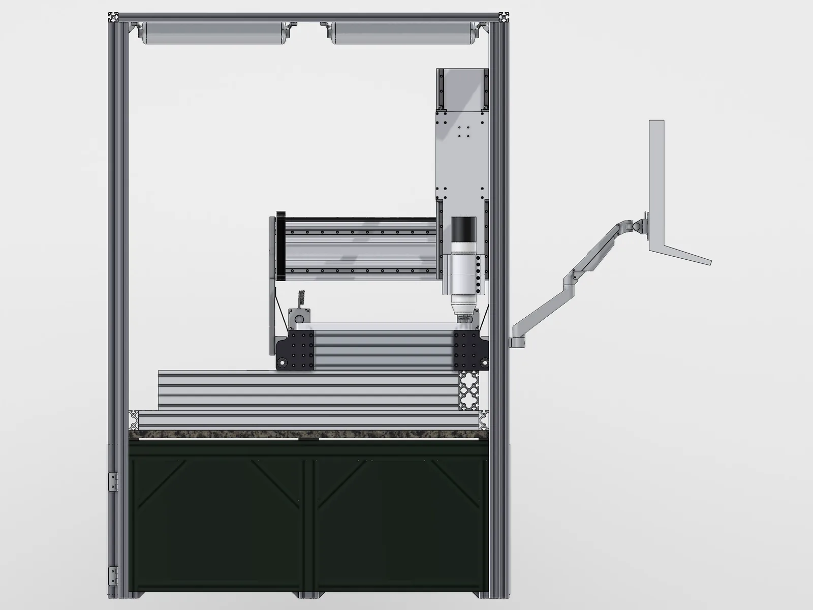
X runs on two ball screws, one motor per side, slaved in software, so the machine squares itself off two home switches every time it powers on. The motors are NEMA 34 closed-loop steppers, 12 Nm on X and Y and 6 Nm on Z, and every driver's alarm output is wired back to the controller so a stalled axis stops the job instead of scrapping the part.
The Z motor has a brake built in. The spindle and its plate come to about 30 kg, which back-drives a 5 mm lead screw at only 0.26 Nm, so without the brake the spindle would drop into the part on every power cut.
The Z rails are fixed to the gantry and the blocks ride on the moving plate, so Z is as stiff fully extended as it is retracted.

Sheet 07 of 11/Stand
Three bays under the table
The machine sits on a granite slab, and the slab sits on a 700 mm stand of bolted 40-series extrusion. Granite needs support about every 700 mm, or a strip model of the slab sags about 0.7 mm.
The slab touches nothing but 80 x 80 x 10 mm steel pads, ground flat to each other after the stand is levelled, so the frame's own flatness can't bend the slab.
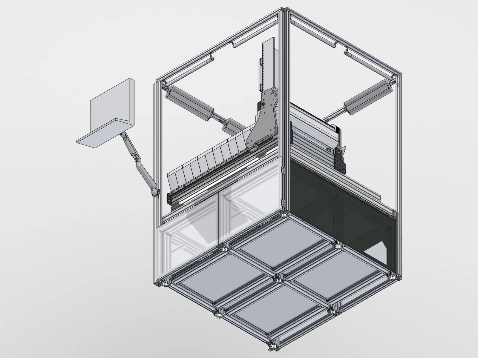
Under the table are three bays: one for the tool changer, one for 4-axis machining and one for 5-axis machining.
One catch from modelling it: the 80x80 legs only have four 6.7 mm core bores and nothing in the middle, so a levelling foot can't screw into the leg end. Every leg gets a bolted steel base plate to carry its foot instead. As modelled the stand is 47 parts and 137.4 kg, with zero interferences.
Sheet 08 of 11/Control
Controller, spindle and the stop button
It runs LinuxCNC on a desktop or mini PC, not a laptop, through a Mesa 7i96S and 7i76U, $268 for both cards. LinuxCNC was the only open-source controller that reaches a 5-axis mill with a tool changer, and it drives six outputs: X, X2, Y, Z, and the trunnion's A tilt and B rotate.
The spindle is a 4.5 kW BT30 tool-change spindle, 8-pole for 18,000 rpm, water-cooled, on 220 V single phase. The E-stop is a hardwired button that drops a contactor and cuts the drives and the spindle together, so it still works if the PC hangs.
Sheet 09 of 11/4th and 5th axes
Three axes now, five later
As drawn it's a 3-axis mill, and the 4th axis has its own assembly started in the model. The plan for five is a trunnion I build myself, tilting on A and rotating on B, and it has to fit the height the frame leaves it rather than the frame waiting on it. The 4th axis and the 5-axis setup each get their own bay under the table.
The real ceiling on five axes isn't the controller, it's the CAM. LinuxCNC runs 5-axis code fine, but generating it takes expensive software and a real skill.
assets/projects/cnc-machine/13-trunnion-general-arrangement.webpSheet 10 of 11/Tool changer
A tool changer with no drop-in rack
The tool changer gets its own bay under the table. There's no published drop-in rack for BT30 tools, and every fully documented build uses ISO20, ISO30 or TTS. A tool mover assembly is started in CAD, and the rack spacing waits on the spindle nose drawing.
Sheet 11 of 11/Status
What this is not
It is not a machine yet. Everything on this page is the SolidWorks assembly and the sizing behind it, from about 40 hours of general design and about 60 hours of research and development. I expect it to cost around $7,000 to build, and I plan to build it within a year.
The plan is to prove it with cut tests, not calculations: shim the rails to a straightedge, push on the spindle nose and measure how far it moves, run a ballbar, then step up the depth of cut in 6061 until it chatters.
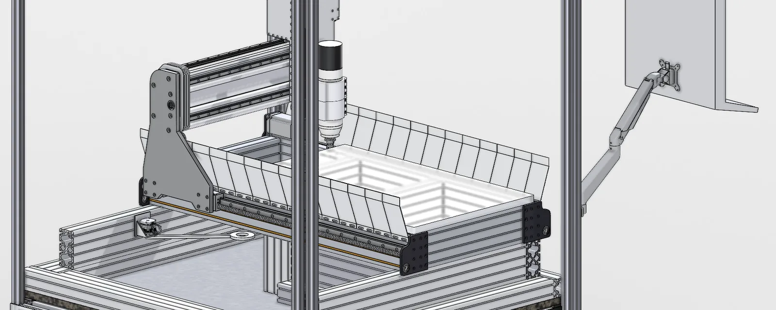
PL 01The main assembly as of September 2026. The gantry, the Z column and the spindle over the vacuum plate, with the operator screen on its arm at the right.