Machined part designSolo, design and CADDrawing 33 of 47
LR-308
lower receiver
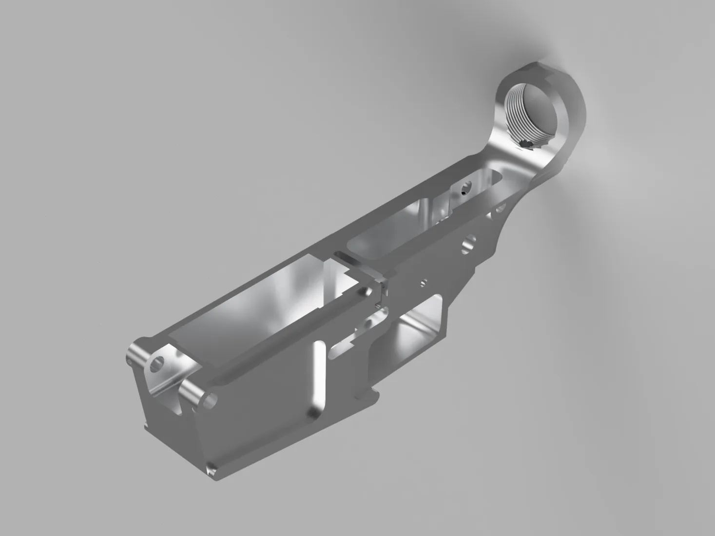
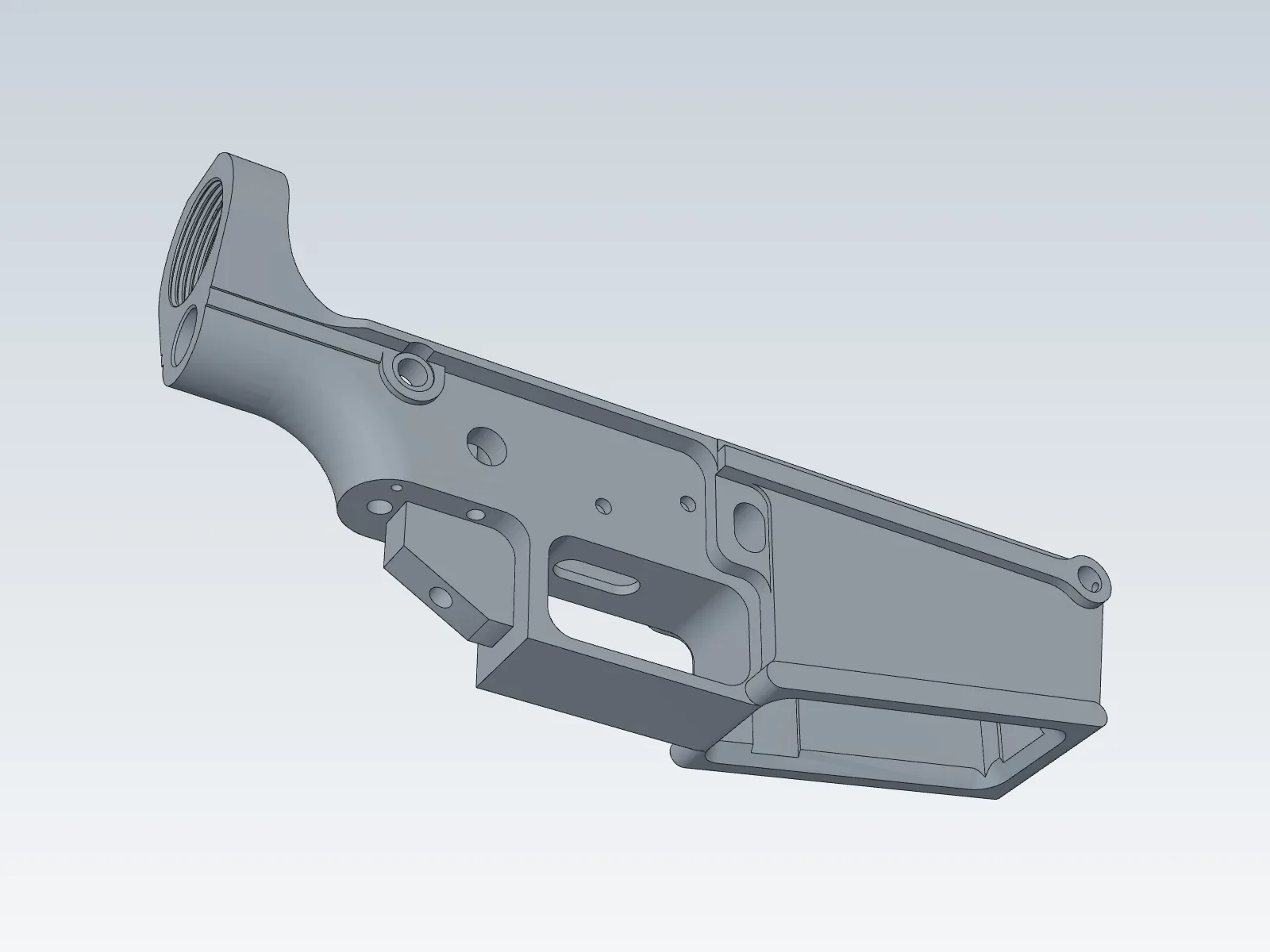
An AR-10 lower receiver I designed myself to the DPMS LR-308 pattern. I drew it to be machined from a solid 6061-T6 aluminium billet, and I wrote a 5-axis toolpath for it in Fusion 360.
- StatusComplete 2026. Designed and toolpathed, not machined
- PatternDPMS LR-308 (AR-10), .308
- Material6061-T6 aluminium
- ProcessSubtractive, CNC machined from billet
- ModelVersion 1.2, rendered in Fusion 360
- Finished massAbout 350 g, from the model's volume
- Not publishedThe model files and a dimensioned drawing, because of firearms law
Sheet 02 of 05/The part
What the part is
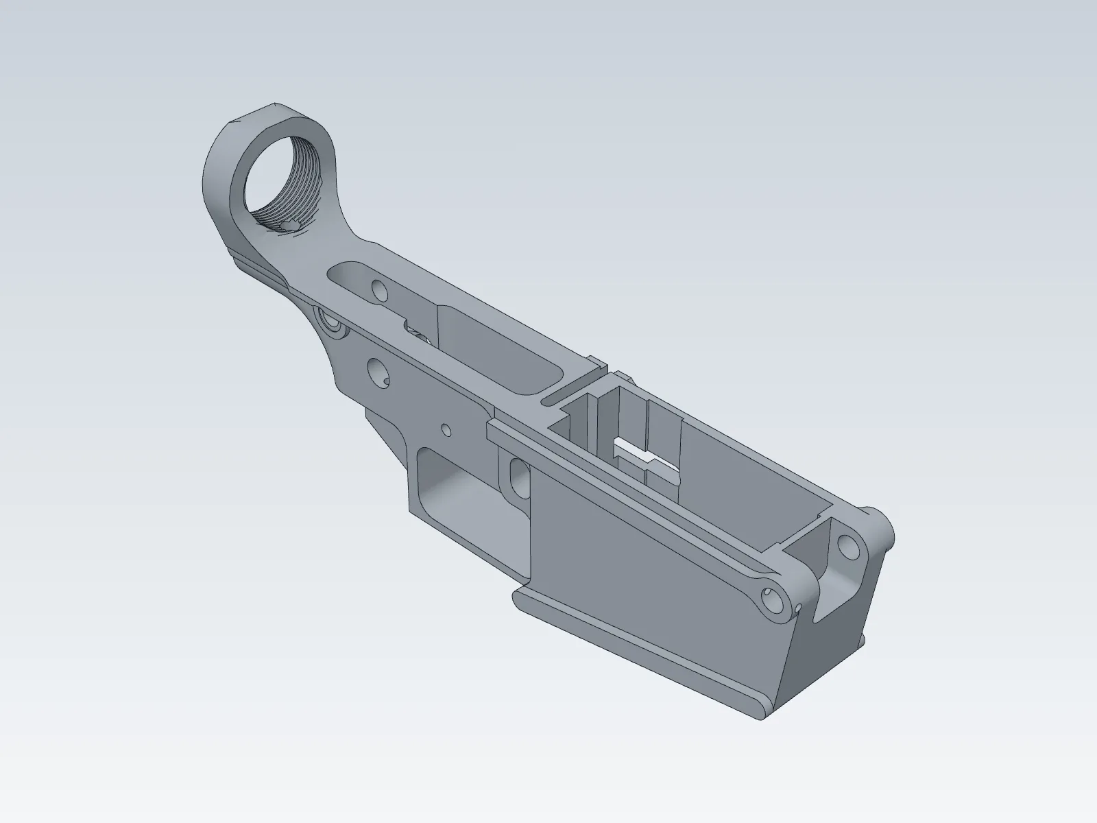
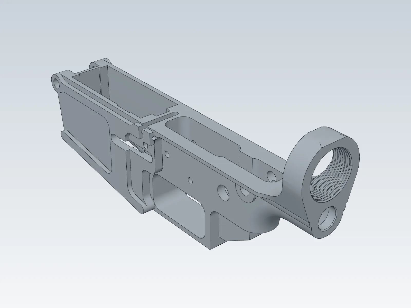
The lower receiver is the frame that the rest of an AR-10 rifle attaches to. This one follows the DPMS LR-308 pattern, which is the common AR-10 standard for .308.
The part is one solid body, so it can be cut from a single block.
Sheet 03 of 05/Material
6061-T6 aluminium, cut from a billet
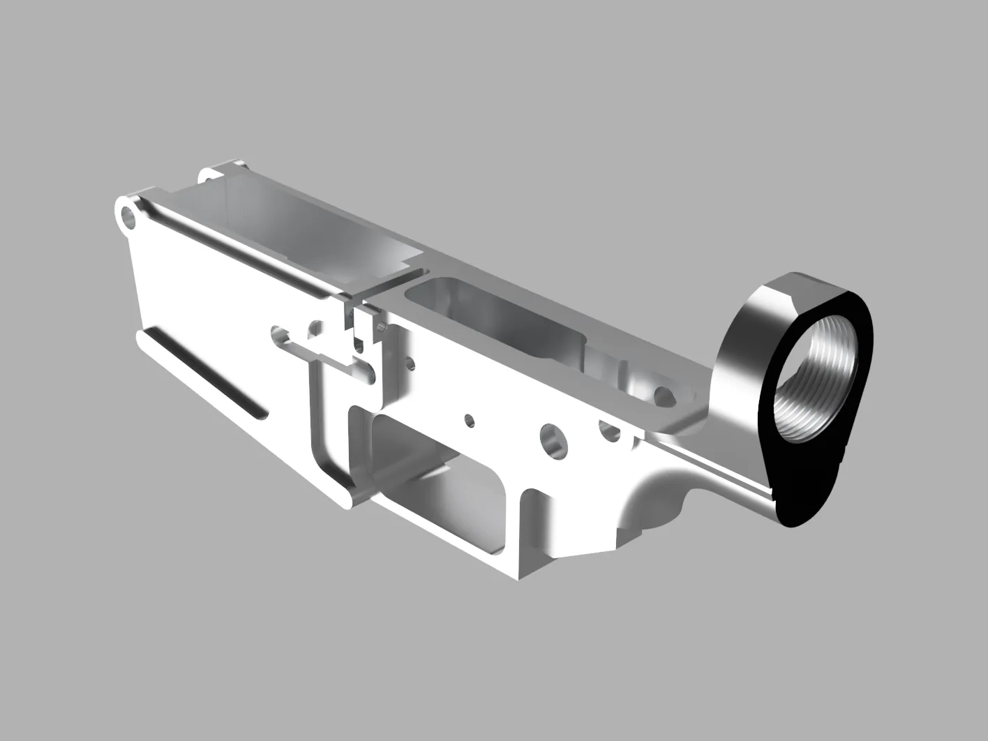
I drew it in 6061-T6 aluminium. The plan is subtractive, so it gets cut out of a solid billet instead of being printed or cast. 6061-T6 machines cleanly and takes anodizing well. At 2.70 g/cm³ the model comes out at about 350 g.
It'll be cut on my CNC machine once that's built.
Sheet 04 of 05/Toolpath
Simulating the toolpath
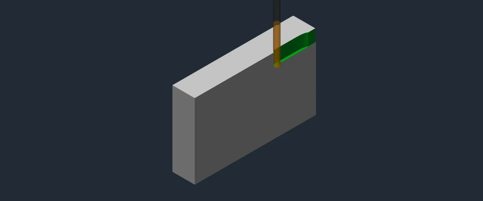
This is the first toolpath I've written since the fidget spinner mold. I set it up in Fusion 360 on a generic 5-axis machine, so the part can tilt and the tool can reach each side.
The video below is only a simulation.
Sheet 05 of 05/Takeaways
What I'm taking from it
Gunsmithing is a lot of fun. This lower is one of several platforms I've designed, and right now I'm designing a double-barrel shotgun. I'll keep designing more parts and more guns.
This page only has pictures and a simulation. I'm not publishing the model files or a dimensioned drawing, because of federal firearms law and ghost gun file distribution laws.
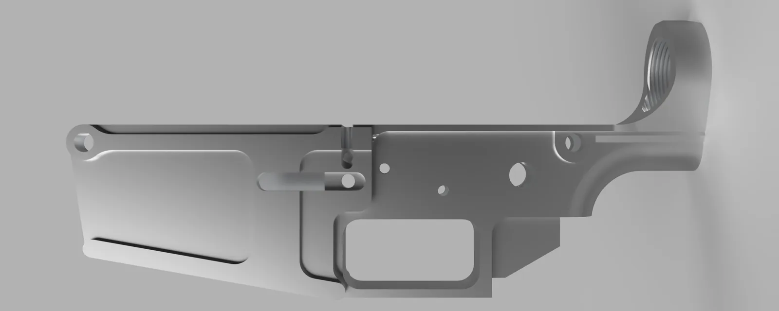
PL 02The side profile, rendered in Fusion 360. The magazine well is at the front, the trigger guard opening is in the middle and the buffer-tube ring stands up at the back.