Course design projectDrawing 21 of 33
Fidget Spinner
Design
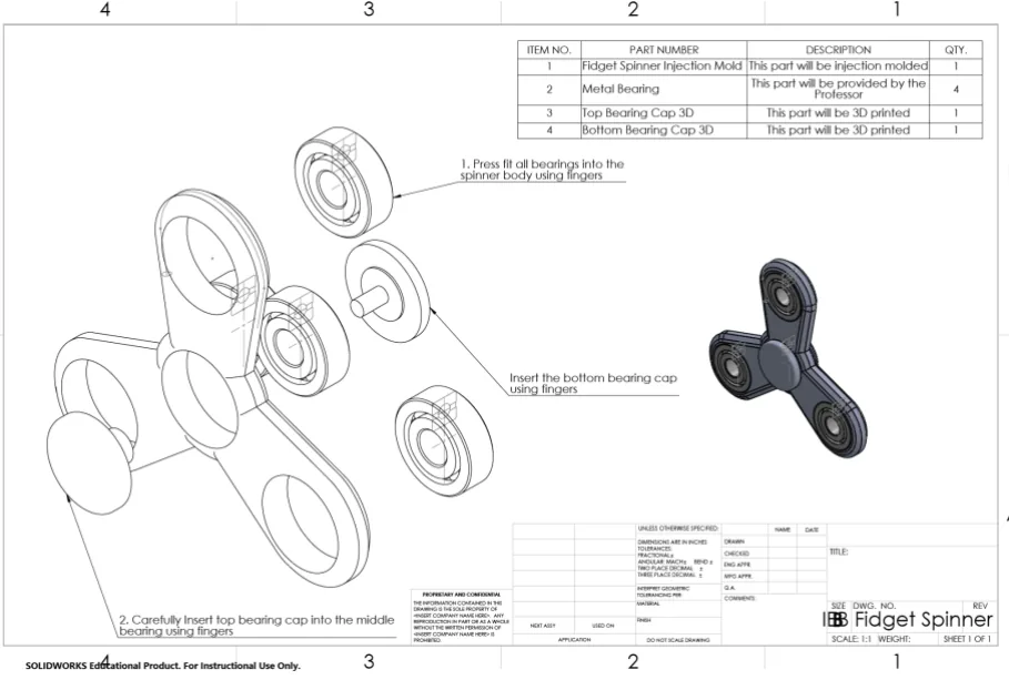
For ME 210 at UT Austin I took a fidget spinner from a sketch all the way to an aluminium injection mold, finishing every step of the design package myself. The part that actually came out of the mold still didn't work.
- StatusComplete, December 2021
- ToolsSolidWorks 2020-21 for CAD, GD&T and FEA, Fusion 360 for CAM
- AssemblyOne injection molded body, four bearings, two 3D printed caps
- OutcomeDrawings and mold finished, the manufactured spinner failed
Sheet 02 of 08/Brief
The point of the assignment
The assignment was to take a fidget spinner from a sketch through CAD, GD&T, an FEA drop test and a real aluminium injection mold, about twelve weeks total, with the mold and CNC work eating the biggest single chunk, three weeks.
Sheet 03 of 08/Design
The design and the drawings
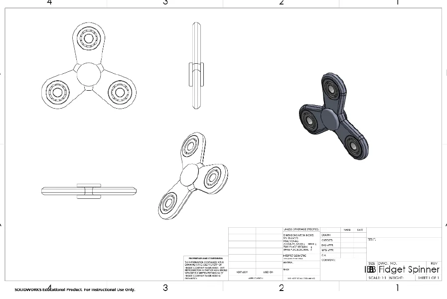
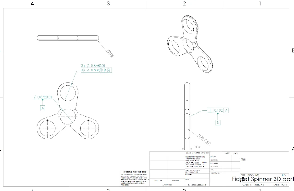
Three arms around a centre hub, four bearings total, one in the middle and one per arm, with the three arm bearing pockets carrying a position tolerance referenced back to the centre bore, which is the drawing's way of saying how far off centre a pocket is allowed to sit.
Sheet 04 of 08/Analysis
Drop test
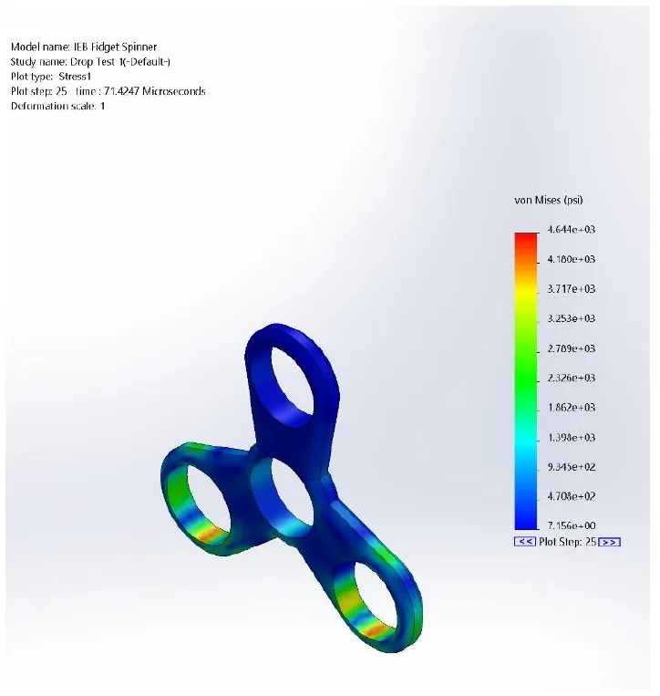
The FEA drop test on the body peaked at about 4,600 psi, around 71 microseconds after impact.
Sheet 05 of 08/Mold
Cutting the mold
Half of what actually makes a part manufacturable, like how much the plastic shrinks as it cools, never shows up on a model on a screen, only once the metal is actually being cut.
Sheet 06 of 08/Failure
What came out
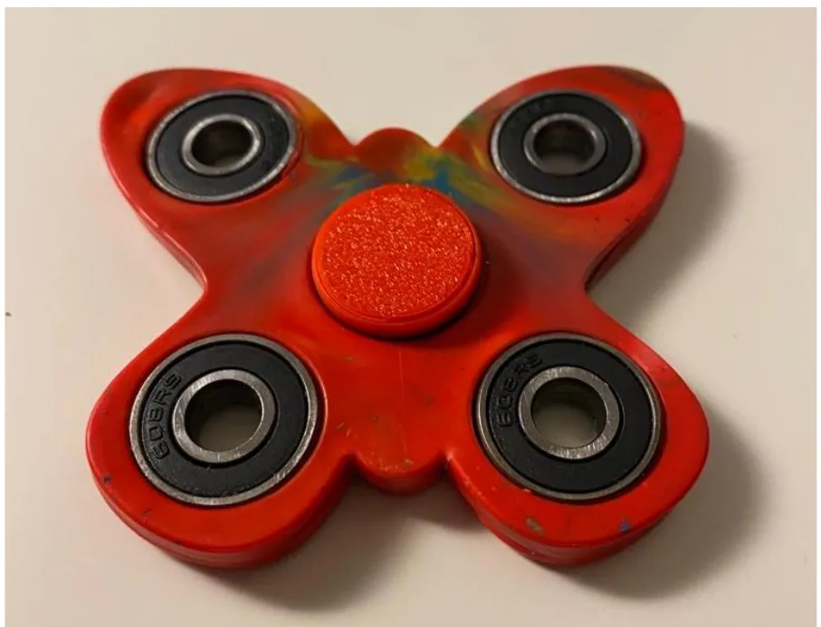
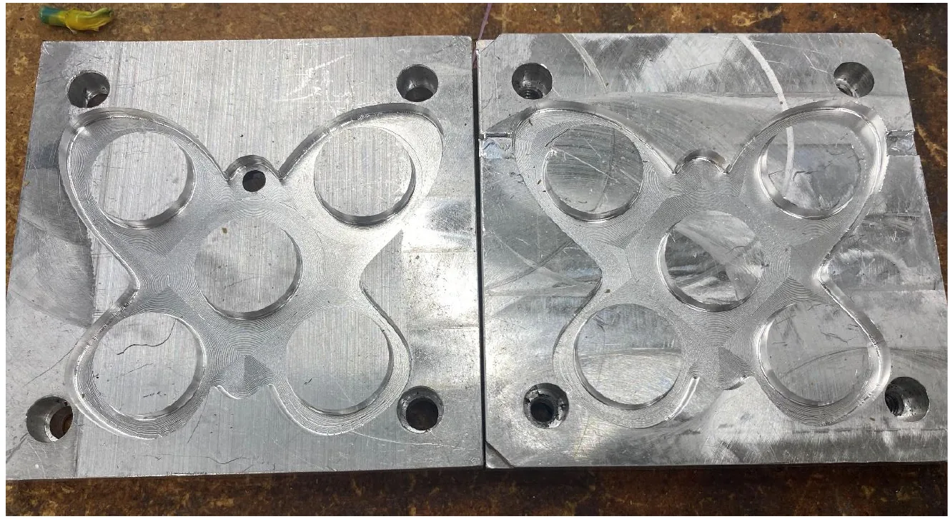
My group's spinner didn't work, and the mold that got cut and the part that came out of it are a four arm shape with five bearing pockets, not the three arm part my own drawings called for.
Sheet 07 of 08/Again
What I would change
- Split the mold differently: one half the spinner body, the other a cap, for more even shrinkage and an easier release.
- Use three bearings instead of four, mainly to save time.
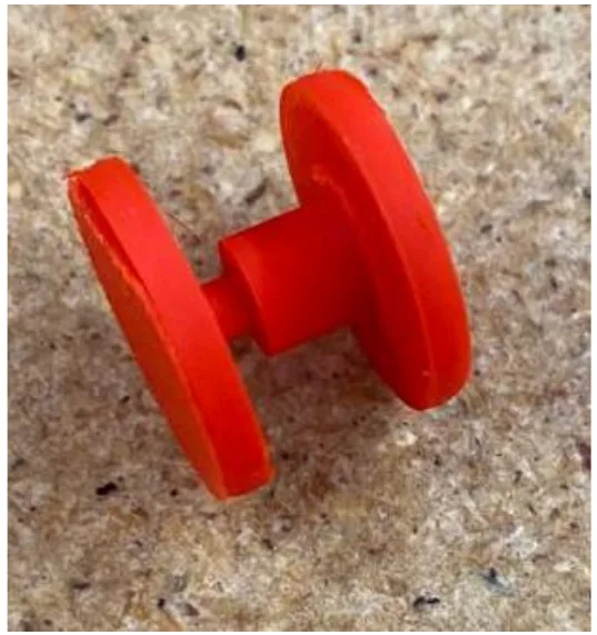
PL 07The two bearing caps, 3D printed and pressed together, the only parts of the assembly I made myself.