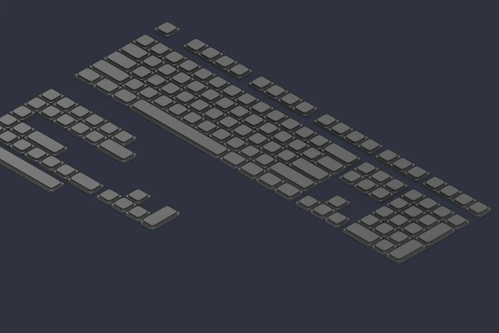
Isometric render of a full set of grey low-profile keycaps laid out in rows on a dark blue background, including wide Shift, Enter and space bar caps

Sheet metal formingDesignerDrawing 47 of 47

Metal
Keycaps

Keycaps pressed out of flat aluminium sheet, one stroke of a punch into a 3D-printed die. Before printing any tooling, I simulated the press to see whether the corners would tear, wrinkle or come out at all.

Sheet 02 of 08/Why

Caps from flat sheet

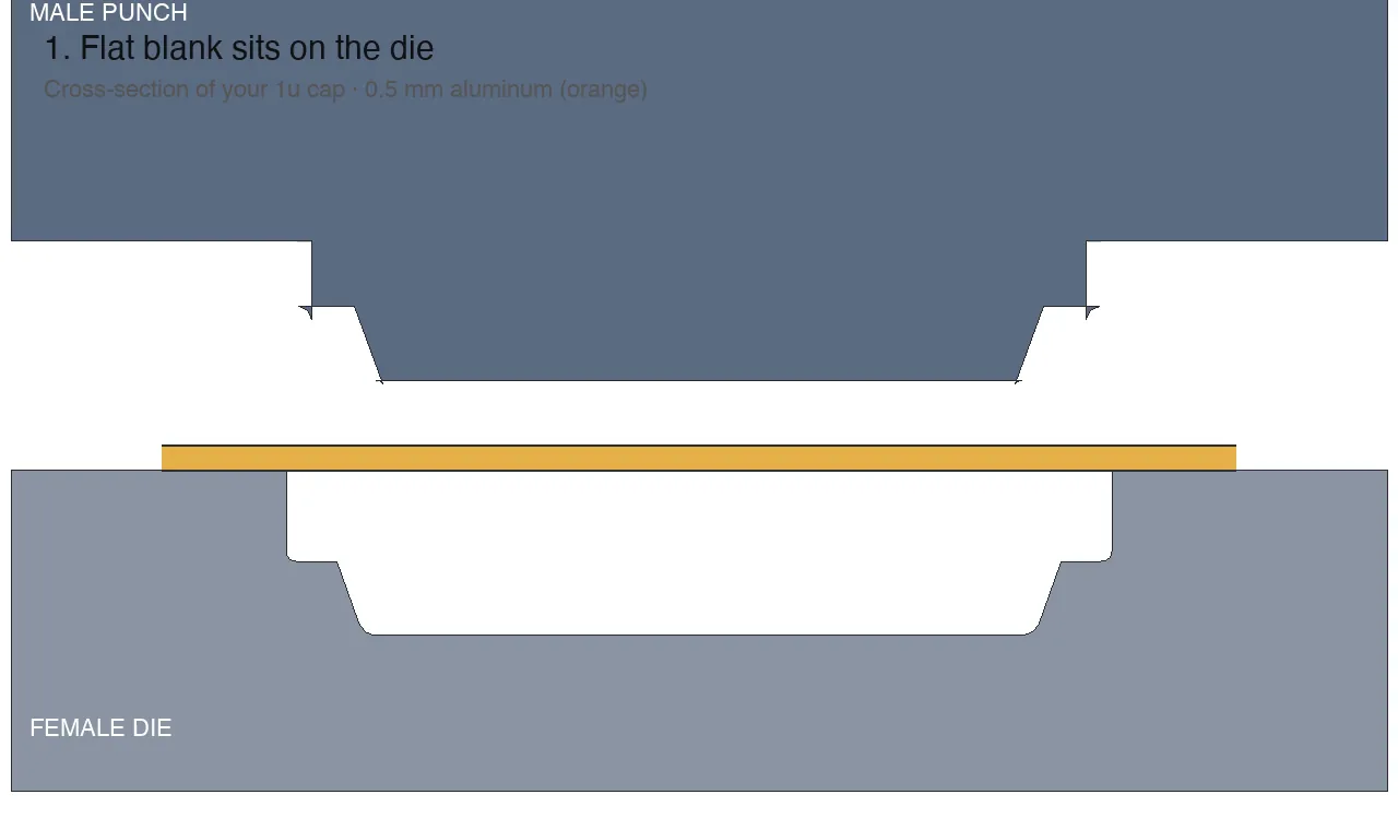
Each cap starts as a flat laser-cut square of aluminium. A punch presses it into a die in one stroke and folds the skirt down, then the cap gets a Choc stem glued underneath and gets anodized.
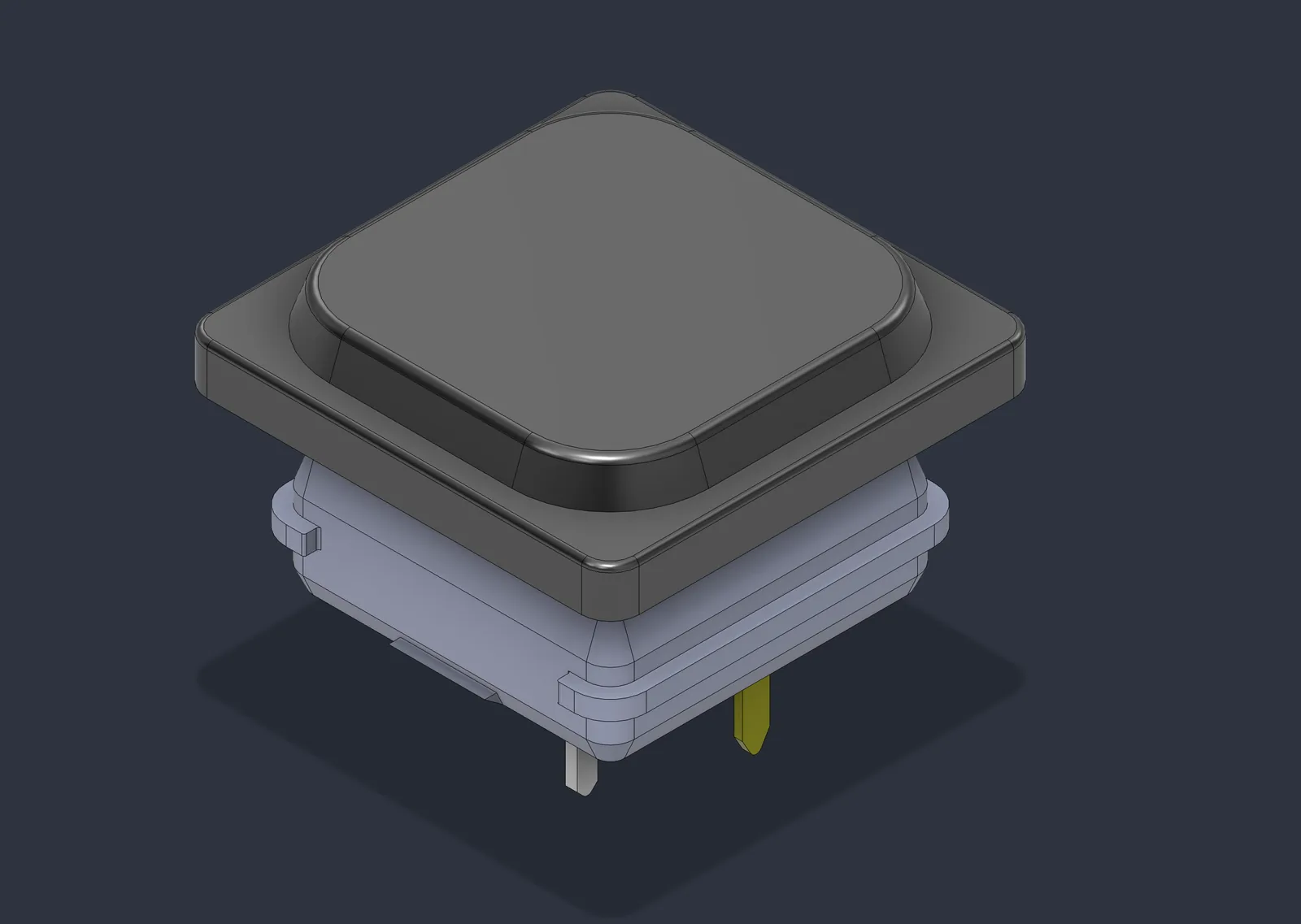
Isometric render of a dark grey low-profile keycap with a rounded square top sitting on a pale blue-grey low-profile switch with two pins underneath
PL 15One 1u cap seated on a low-profile switch in Fusion 360.
Animated cross-section of a grey punch pressing an orange aluminium blank into a grey die and lifting away, leaving a formed cap
PL 02How the press works, in a cut through the middle: the punch comes down, folds the blank into the die, and lifts off again.
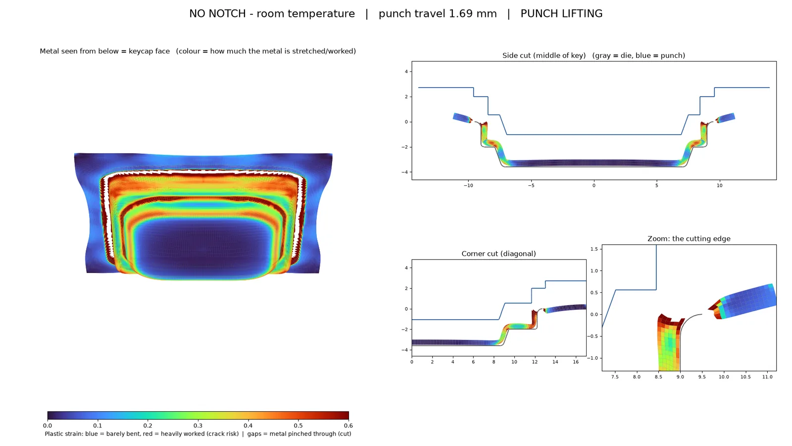
Simulation result of a stamped keycap seen from below in a blue to red strain colour map, beside side and corner cuts through the punch and die
PL 01The last frame of the no-notch press: the cap seen from below, coloured by how hard each part of the metal was worked.

Sheet 03 of 08/Tooling

The dies

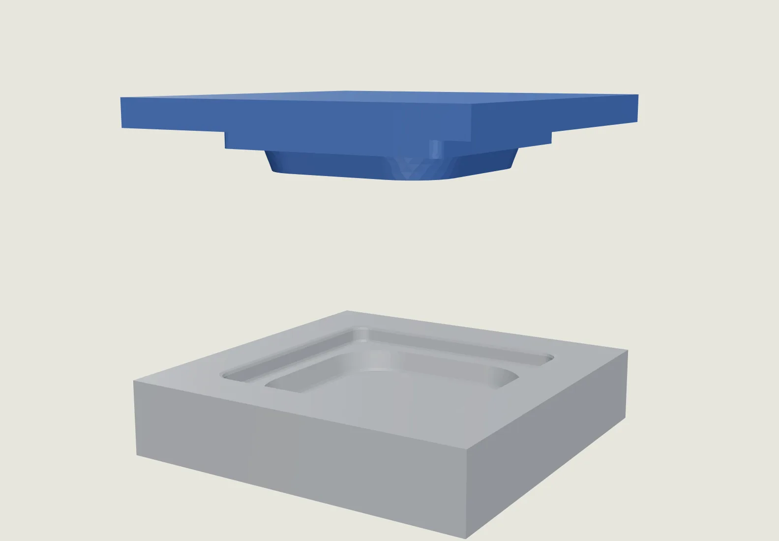
Fusion 360 scripts build the tooling straight from my own keycap body: a female die, a male punch and the flat blank, with two 5 mm steel pins to line them up. The dies are 3D printed. A second pair trims the scrap ring off the edge, and a four-up version trims four caps at once.
3D render of a blue punch block with a stepped keycap-shaped boss hovering above a grey die block with a matching cavity
PL 10The forming punch above the forming die, rendered from my STEP files.
3D cut-away of the punch seated in the die and a side cut plot showing the narrow gap between them
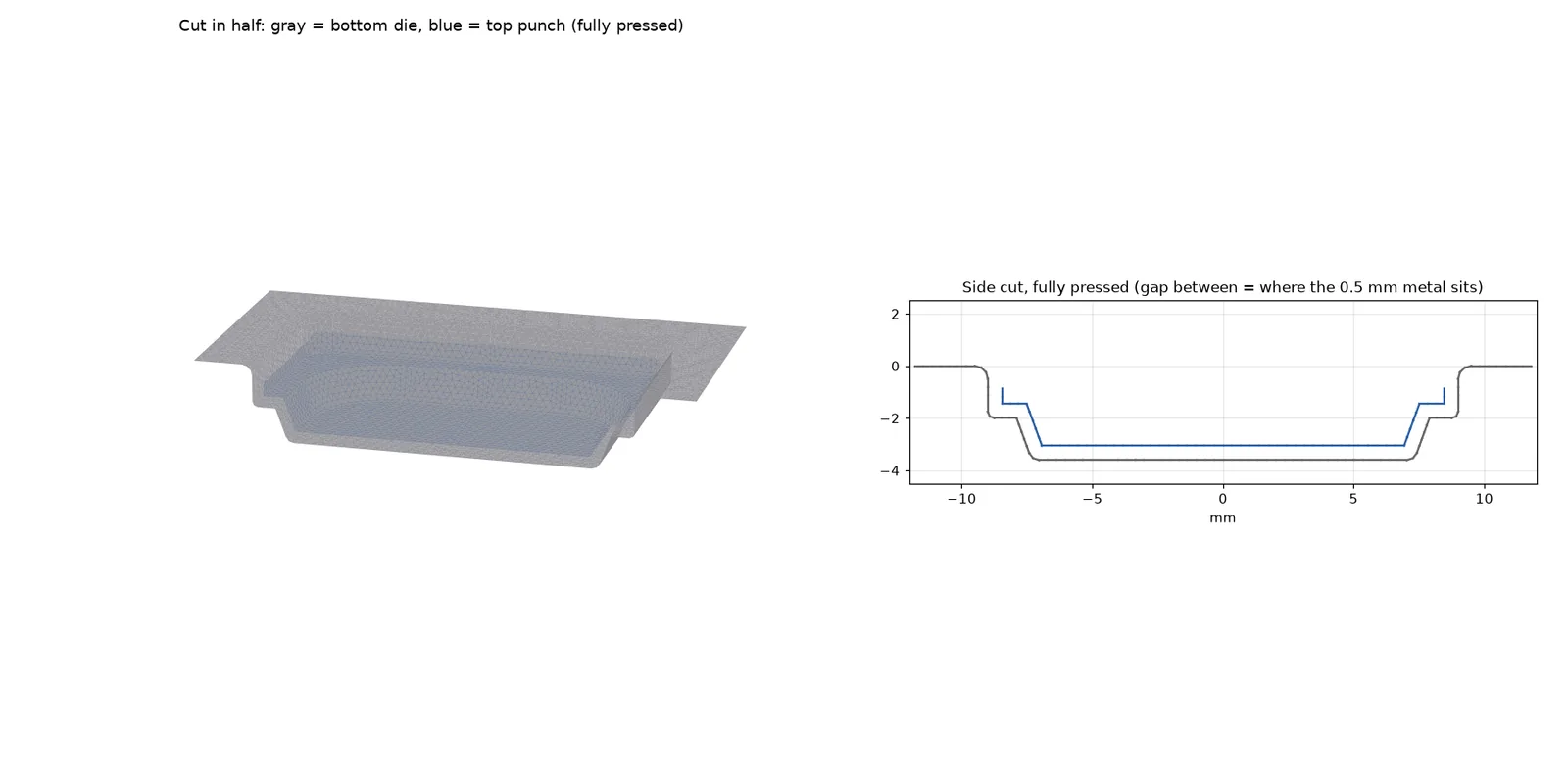
PL 11The same pair pressed closed and cut in half, with the 0.5 mm gap where the sheet sits.
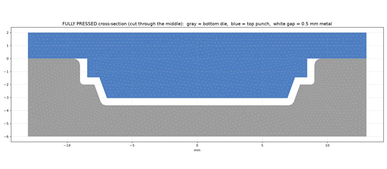
Cross-section of a blue punch seated in a grey die with a thin white gap following the keycap shape
PL 03The forming die fully closed. The white gap between die and punch is where the 0.5 mm sheet sits.
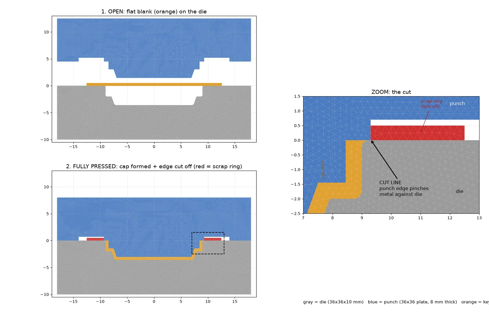
Two cross-sections of a trim die, open with a flat orange blank and fully pressed with a red scrap ring cut away, plus a zoom of the cutting edge
PL 04The trim die: the punch edge pinches the metal against the die and cuts the scrap ring off.
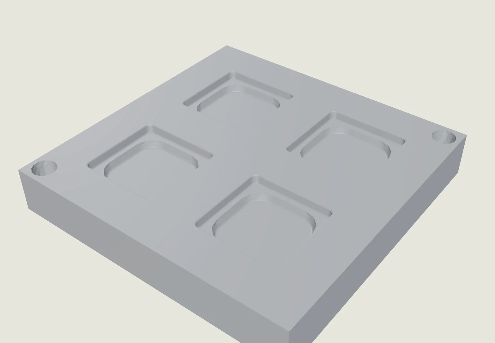
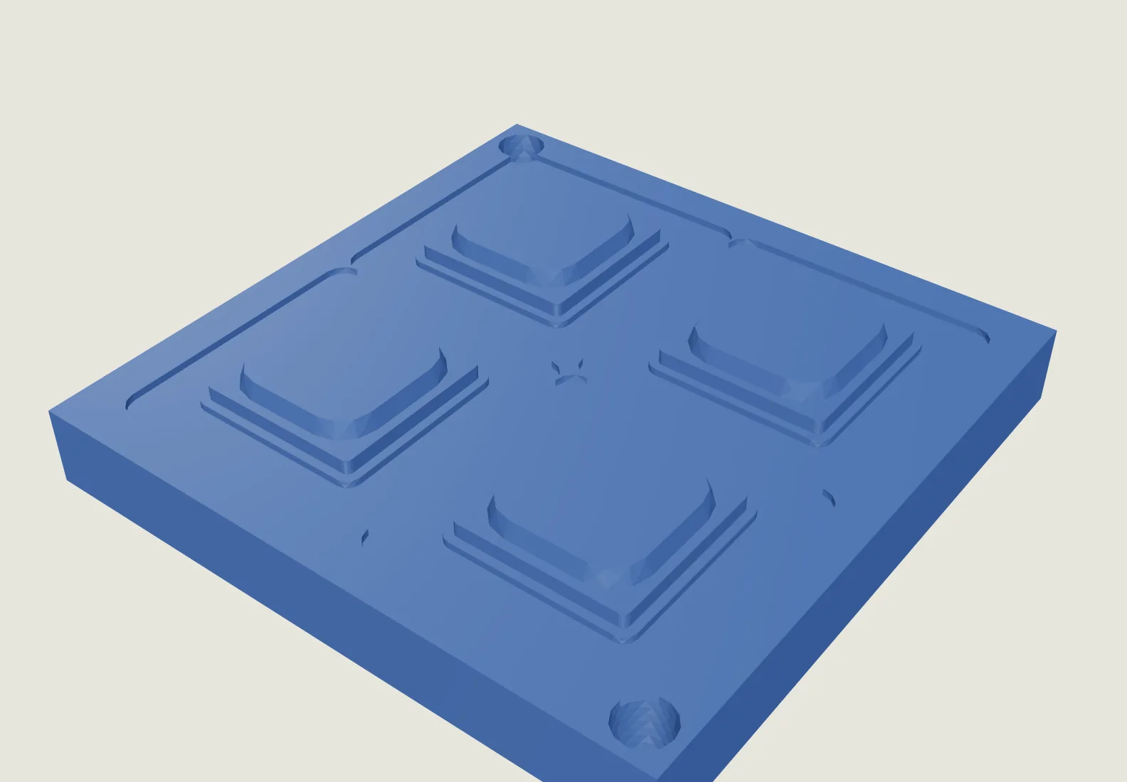
3D render of a grey square die block with four keycap cavities and two guide pin holes in opposite corners
PL 12The four-up trim die, which cuts the scrap ring off four caps in one stroke.
3D render of a blue punch plate seen from below with four raised keycap-shaped cutting bosses and guide pin holes
PL 13Its punch, flipped over to show the four cutting faces.

Sheet 04 of 08/Simulation

Pressing it in a computer first

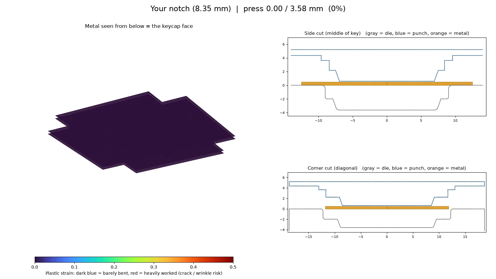
The first runs in CalculiX showed how much the die's edge matters: with a 0.5 mm rounded edge the press got to 79 percent, and with a 0.2 mm edge it stopped at 57. The full runs moved to OpenCourant on my PC, covering the press, the cut and the punch lifting off.
Simulation video of a square aluminium sheet bending into a keycap shape, with strain colours and two cross-section plots
PL 05An early run that stopped at 79 percent of the press, with the sheet seen from below and cut through the middle and the corner.

Sheet 05 of 08/Notch

The missing corners

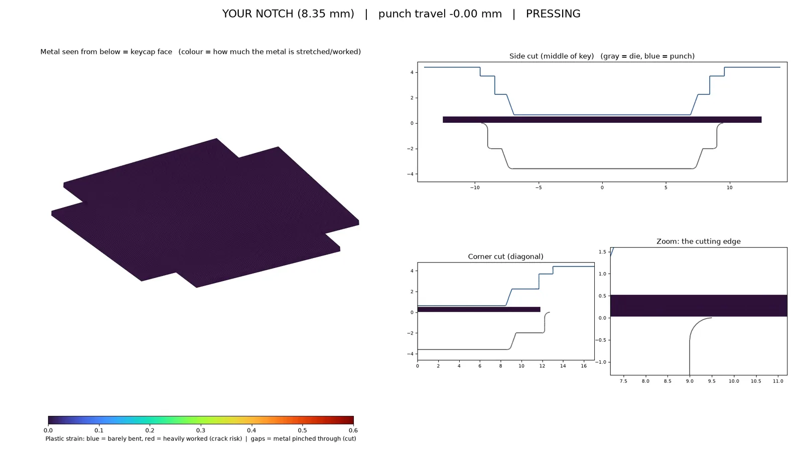
The first blank had a square notch cut out of each corner, so the metal wouldn't bunch up there. The simulation showed the notch reached past the cut line into the cap itself, so the finished cap came out with no corners.
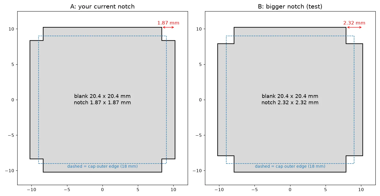
Two drawings of a square blank with square notches cut from each corner, one notch 1.87 mm and the other 2.32 mm
PL 06The two notched blanks I tried, 20.4 mm square. The dashed line is the outer edge of the cap.
Simulation video of a full keycap press, cut and punch lift, where the finished cap shows gaps at all four corners
PL 07The full press with the notched blank. The notch reaches inside the cut line, so the cap comes out without its corners.

Sheet 06 of 08/Result

Full corners

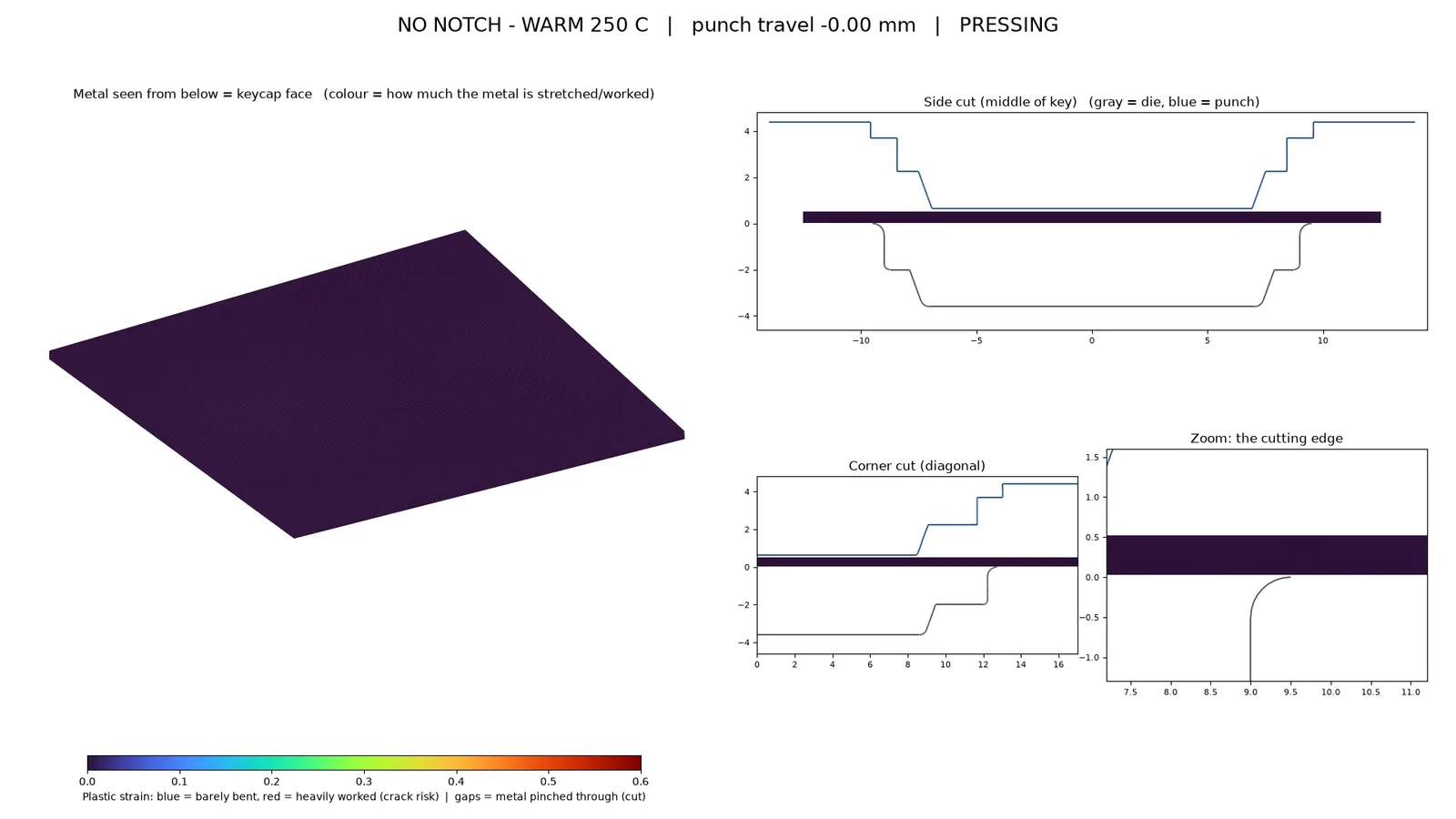
With no notch at all, the skirt formed all the way round, the cut went cleanly round the edge, and no wrinkles showed at the corners. Heating the metal to 250 °C didn't change the shape.
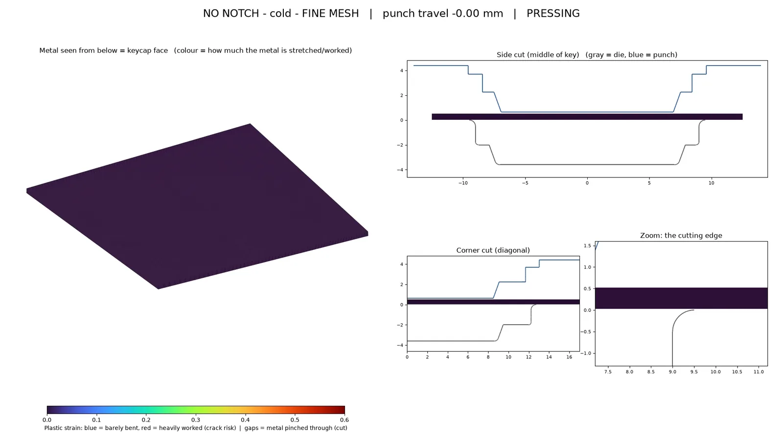
Simulation video of a full keycap press with an un-notched blank, forming complete corners, then the edge cut and the punch lifting
PL 08No notch, room temperature, the fine mesh. The skirt forms all the way round and the cut goes clean around the edge.
Simulation video of the same keycap press with warm metal, ending in the same full-cornered cap
PL 09The same press with the metal at 250 °C. The shape comes out the same as the cold run.
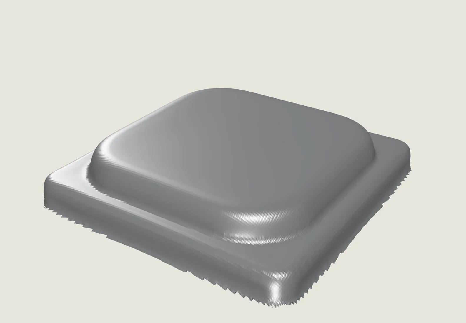
3D render of a grey aluminium keycap with a rounded square top and a flange, its outer edge ragged where the simulation cut it
PL 14The cap that comes out of the simulation. The ragged edge is the simulated cut, not a real one.

Sheet 07 of 08/Detail

A finer mesh

The last run used a 0.055 mm mesh with nine layers through the 0.5 mm sheet, 464,000 elements for a quarter of one cap. It took about six hours on my PC.

Sheet 08 of 08/Limits

What the simulation can't show

The solver doesn't really remove metal at the cut. It squeezes it down to a thin film, and the videos hide that layer to show the separation. How clean the cut edge comes out can only be checked on a real press, and that's the next step: I haven't pressed a cap yet.