PCB designDesignerDrawing 16 of 33
Custom
keyboard
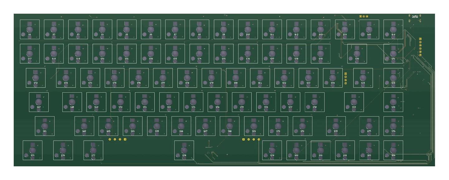
Three goes at a mechanical keyboard, all drawn in KiCad, settling at 84 keys. The second one is assembled and waiting on switches, and none of the three has typed a character yet.
- StatusProduction, 2026. Generation two assembled, waiting on switches
- Layout84 keys, hotswap Kailh Choc sockets
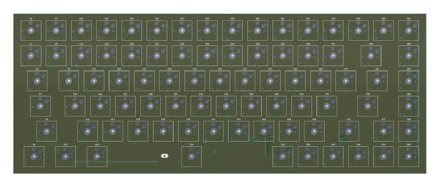
- Generation twoSTM32F072 over USB-C, three complete Gerber sets
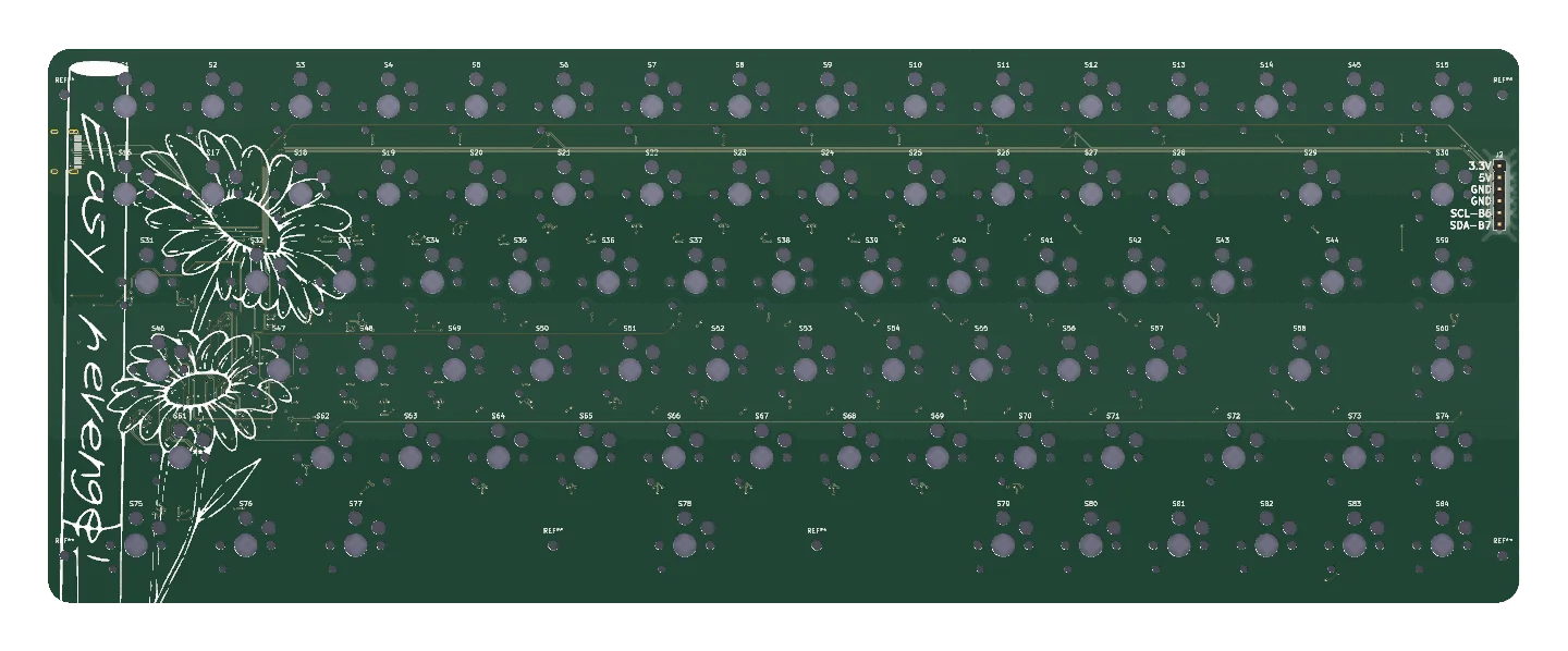
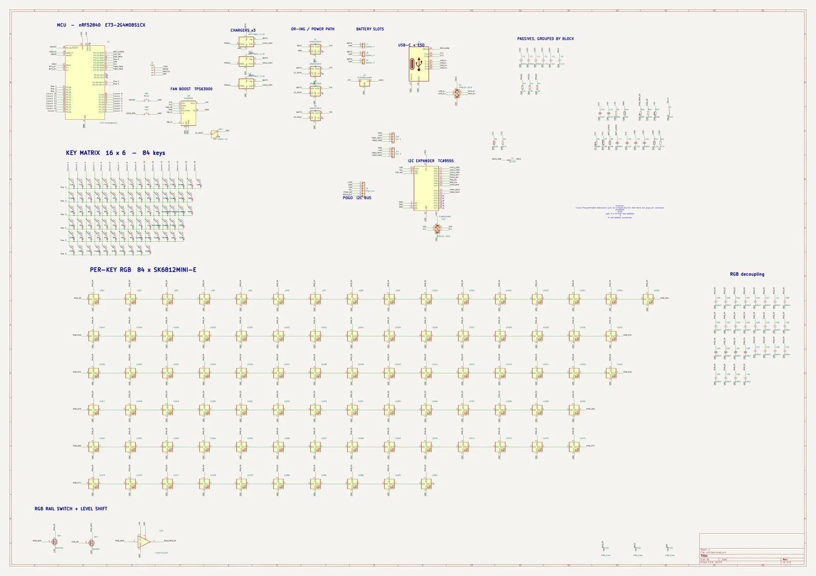
- Generation threenRF52840, wireless and wired, per-key RGB
- Firmwarenone written, for any of the three boards
- Characters typed0
Sheet 02 of 08/Why
Why a keyboard is a good first PCB
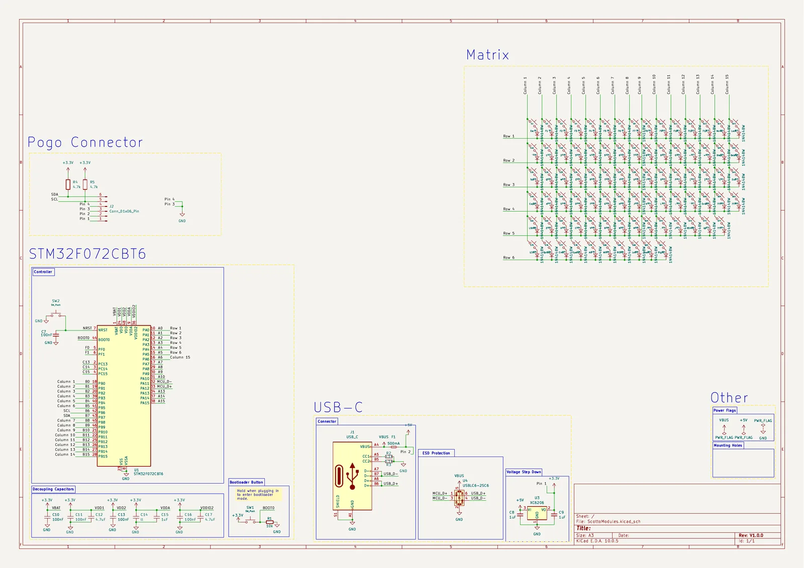
Under every key it is the same small circuit, a switch and a diode, drawn once and then repeated eighty-four times.
Sheet 03 of 08/Three boards
Three attempts
The first one I gave up on, the third is mine from scratch, and the second grew out of Joe Scotto's ScottoModules template, which gives you the STM32 and leaves a blank box labelled "Matrix" for you to fill in.
Sheet 04 of 08/The layout
What 84 keys means
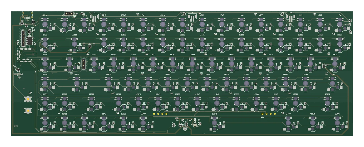
Eighty-four keys in hotswap sockets, a function row, an arrow cluster bottom right and no numpad at all, with an addressable LED under every key on the third board.
Sheet 05 of 08/Going wireless
What the third board dragged in
Moving to an nRF52840 pulled in three lithium chargers, three battery slots and a power path to pick between them and USB, none of which the wired board needed.
Sheet 06 of 08/Deleting the numpad
The numpad and the trackpad come off
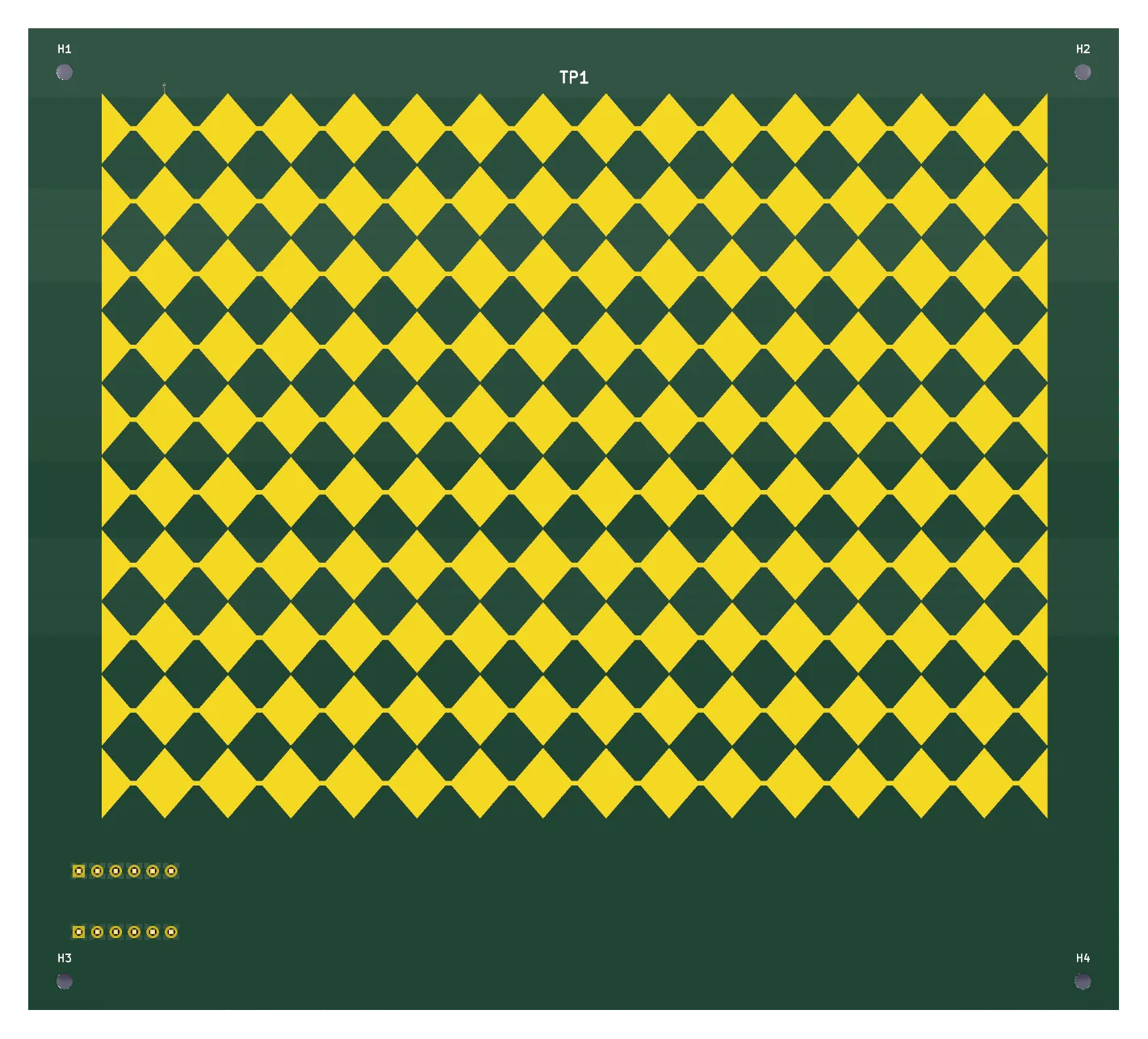
The numpad and the pointing device are not on the keyboard at all, they hang off a six-pin pogo I2C connector as separate modules, and so far only the trackpad has been drawn.
Sheet 07 of 08/Where it stands
What exists now
Generation two is assembled and sitting here as a board full of empty sockets, so switches first, then firmware.
Sheet 08 of 08/Source